PAGE 4
PRINTED IN THE U.S.A.
INSTALLATION
SECTION 4
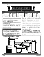
MAXIMUM WORKING PRESSURE
MODEL
AC-140 & AC-150
AC-160 THRU AC-180
AC-190 THRU AC-220
70
O
F
400 PSIG
265 PSIG
260 PSIG
300
O
F
350 PSIG
230 PSIG
225 PSIG
400
O
F
330 PSIG
220 PSIG
215 PSIG
WEIGHT
4.5 LBS
12.5 LBS
14.5 LBS
DIMENSIONS
A
18.00"
22.00"
24.00"
B
2" NPT
3" NPT
4" NPT
PART NO.
83-0737
83-0739
83-0740
HOSE
FH-2
FH-3
FH-4
4.3 FLEXIBLE HOSE INSTALLATION
IMPORTANT
A FLEXIBLE HOSE MUST BE INSTALLED BETWEEN THE
COMPRESSOR AND AFTERCOOLER TO VALIDATE THE
WARRANTY ON THE AFTERCOOLER.
The flexible hose must be installed perpendicular to the direction of
vibration from the compressor.
If a flexible hose was not ordered with the aftercooler, one can be ordered
from your Van Air distributor. Figure 2 lists the hose required for each
aftercooler model.
4.4 PIPING INSTALLATION
CAUTION
ALL PIPING MUST BE ADEQUATELY SUPPORTED AND
ISOLATED FROM VIBRATION. EXCESSIVE STRESS OR
VIBRATION IN THE PIPING WILL CAUSE DAMAGE TO THE
AFTERCOOLER CORE.
TO ENSURE PROPER OPERATION, MAKE SURE THAT THE
INLET AND OUTLET PIPING ARE CORRECTLY CONNECTED
TO THE UNIT. REFERENCE FIGURE 3.
If the aftercooler is to be installed in an existing piping system, clean the
piping to remove accumulated dirt, pipe scale, oil, and other contaminants
before installing the unit.
A properly sized pressure relief valve should be installed after the
compressor and before any block valves. The relief valve should be
installed in compliance with any applicable federal, state, or local codes.
To isolate the aftercooler for maintenance, install bypass piping around
the aftercooler and separator (if installed). Reference Figure 3.
Connect the inlet piping to the top of the aftercooler. Make sure that the
flexible hose is properly installed before the aftercooler inlet. Provide
supports wherever necessary to prevent stress on the aftercooler.
Supports should be installed close to the inlet and outlet manifolds. Use
either overhead or stiff-leg type supports.
4.5 FREEZE PROTECTION
If the aftercooler is to be installed in a location where ambient tempera-
tures may fall below 35
o
F, heat tracing and/or insulation must be used on
the outlet piping to the separator, the separator, and the drain piping. The
aftercooler must be protected from the direct wind, i.e. a roof and/or walls.
The aftercooler should be turned off when ambient temperatures fall below
35
o
F. DO NOT cycle the fan motor on and off.
FIGURE 3 RECOMMENDED INSTALLATION DETAIL
FIGURE 2 FLEXIBLE HOSE DETAILS


