background image

17

Gas Supply

Installation

Connect Gas Supply

The gas supply inlet connection is a 1/2” NPT female. 

Gas shut-o

  valve supplied on the end of stainless steel 

fl

 exible connector. Flex connector is located on the left 

hand rear corner of the appliance.

Use only new black iron or steel pipes, CSST, or copper 

tubing if acceptable—check local codes. Note that 

in USA, copper tubing must be internally tinned for 

protection against sulfur compounds.
The burner module and gas train on this appliance may 

be removed as a unit for servicing. The 

fl

 ex pipe supplied 

with the unit provides a union for removal of the module.
Unions in gas lines should be of ground joint type.
The gas supply line must be sized and installed to 

provide a supply of gas su

  cient to meet the maximum 

demand of the appliance without undue loss of pressure.
Sealant used must be resistant to the action of all gas 

constituents including LP gas. Sealant should be applied 

lightly to male threads to ensure excess sealant does not 

enter gas lines.
Pressure test the supply line for leaks.
The appliance and its individual shut-o

  valve must be 

disconnected from the gas supply piping system during 

any pressure testing of that system at test pressures in 

excess of 1/2 psig (3.5 kPa).
The appliance must be isolated from the gas supply 

piping system by closing its equipment shut-o

  valve 

during any pressure testing of the gas supply piping 

system at test pressures equal to or less than 1/2 psi (3.5 

kPa).
Failure to either disconnect or isolate the appliance 

during pressure testing may result in regulator or valve 

damages and void the warranty. Consult your dealer in 

case of damages.

X

X

Valve Assembly

Control 

Valve

34” (864 mm) 

fl

 ex pipe 

supplied with 

appliance

Shut-o

  valve 

supplied with 

appliance

1/2” NPT 

female

Manifold 

Pressure 

Adjustment 

behind 

Plastic Cap

Содержание 780MN

Страница 1: ...ation and service must be performed by a qualified installer service agency or the gas supplier Hot glass will cause burns Do not touch glass until cooled Never allow children to touch glass A barrier...

Страница 2: ...h Vancouver BC Canada V7H 3B1 T 604 984 3496 F 604 984 0246 valorfireplaces com This appliance may be installed in an after market permanently located manufactured mobile home where not prohibited by...

Страница 3: ...w 12 Venting 13 Overview 13 Installation Preparation 14 Existing Fireplace Preparation 14 Remove Window 15 Install Fan Kit if used 15 Installation 16 Connect Venting 16 Gas Supply 17 Liner Panels 20 F...

Страница 4: ...ens are installed Some materials or items although safe may discolor shrink warp crack peel and so on because of the heat produced by the fireplace Avoid placing candles paintings photos and other com...

Страница 5: ...ss front removed cracked or broken Replacement of the glass should be done by a licensed or qualified service person Intended use This appliance is designed and approved as a supple mental heater and...

Страница 6: ...Btu h 14 000 14 000 Manifold Pressure in w c 3 2 10 5 Minimum Supply Pressure in w c 5 11 Maximum Supply Pressure in w c 10 14 Main Burner Injector Marking 850 300 Pilot Injector Marking 51 30 Min Rat...

Страница 7: ...on 798FFZ Bronze 799ED Edgemont Door Kits 4004348AZ 799EDFZ Bronze 799EDFN Nickel Backing Plates choose one 799BPB 1 799BPB 2 799BPB 3 3 Sided Backing plates black for 784 799ED 799BPB 4S 4 Sided Back...

Страница 8: ...w the bottom of appliance by 2 13 16 72 mm Plan accordingly Dimensions 33 838 mm 24 610 mm 15 381 mm 15 381 mm 4 102 mm 3 76 mm 3 76 mm 3 76 mm 23 584 mm to top of firebox Gas line access Gas line app...

Страница 9: ...aterials that are reported as passing ASTM E 136 Standard Test Method for Behavior of Materials in a Vertical Tube Furnace at 750 C Clearances WARNING Some materials or items although safe may discolo...

Страница 10: ...side of the appliance liner box Floor Hearth Clearances Combustible shims supports may be used beneath the appliance to level or raise the appliance within the existing fireplace cavity Combustible fl...

Страница 11: ...t you have everything using the Pack Con tent sheet Also check that you have A fuel bed packed separately Liner panels packed separately Venting accessories Electrical accessories if using a fan kit A...

Страница 12: ...f insert must be a minimum 4 102 mm below bottomr of insert Gas insert does not require a hearth WARNING Some materials or items although safe may discolor shrink warp crack peel and so on because of...

Страница 13: ...able vertical vent termination Venting Table Maximum vertical height 40 ft measured to bottom of termination Minimum vertical height 10 ft measured to bottom of termination Maximum horizontal run 4 ft...

Страница 14: ...ting Dampers Factory built zero clearance fireplaces will require the damper to be removed in order to install the vent liners These dampers are usually bolted into place Dampers in masonry fireplaces...

Страница 15: ...ppliance will need to be removed Therefore we recommend that where possible the fan be installed before the appliance is fitted into the cavity Refer to instructions provided with the 795CFKV2 to inst...

Страница 16: ...rebox by sliding it towards the back of the firebox 3 Fit the two liners ensuring that the exhaust liner is connected to the identified EXHAUST vent collar Secure liners to collars with hose clamps in...

Страница 17: ...pressure Sealant used must be resistant to the action of all gas constituents including LP gas Sealant should be applied lightly to male threads to ensure excess sealant does not enter gas lines Pres...

Страница 18: ...testing for leaks Make sure that the appliance is turned o Open the manual shut o valve Test for leaks by applying a liquid detergent or soap solution to all joints Bubbles forming indicate a gas leak...

Страница 19: ...lternate Inlet Connection In cases where local codes do not permit the flex connector to be used inside the appliance case reconnect the flex connector outside of the appliance case A cut out is provi...

Страница 20: ...late 2 screws at rear Lift the front edge up and pull the plate toward you 3 Place the left side panel as shown Rotate the left clip at the top over the panel to hold it in place 4 Place the rear pane...

Страница 21: ...ed with the fireplace Discard the base panels supplied with the liner panels These will be needed for all fuel beds to be installed 9 The base panels come packed with a rectangular cover plate measuri...

Страница 22: ...1 Place log H11 into the right hole in the front of the burner cover Note the angled feature of H11 should be pointed to the right side H11 2 Place log H10 into the left hole in the front of the burn...

Страница 23: ...ace log G3 as shown Note the hole in G3 fits onto the pin in H1 9 Place log H2 as shown Note the hole in H2 fits onto the pin in H1 10 Place embers as shown between and behind H10 and H11 as desired Y...

Страница 24: ...24 Installation Fuel Beds 1000BLKV2 Birch Logs installed H1 H2 G3 H9 H10 H11 G5 H7 H13 G4 Base Panels...

Страница 25: ...place them on the burner platform or other logs Install the logs as shown below 1 Place the cover panel into the recess in front of the burner 2 Place log G4 directly on the burner its underside groov...

Страница 26: ...0 from the left side of G4 to the top groove of G15 H22 G4 G15 H22 H20 G15 G4 7 Place log H17 as shown Note the hole in H17 fits onto the pin in H15 8 Place log H36 as shown Note the hole in H36 fits...

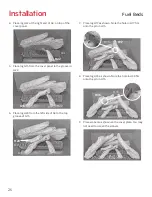
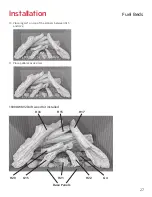
Страница 27: ...27 10 Place log H21 on top of the embers between G15 and H22 11 Place pebbles as desired H21 G15 H22 Installation Fuel Beds 1000DWKV2 Driftwood Kit installed H15 H36 H21 H22 G15 H20 H17 G4 Base Panels...

Страница 28: ...eft H10 H32 G4 G4 Installation Fuel Beds Traditional Log Kit 1000LSKV2 Material required Traditional Log Kit which contains 10 logs 2 cups of embers bagged Gloves if desired Installation Carefully unp...

Страница 29: ...to the groove in G10 7 Place log H28 from the left side of G4 to the top of G16 G10 H11 G4 G16 H10 G10 H28 G4 G16 8 Place log H34 as shown Note the hole in H35 fits onto the pin in H32 9 Place log H33...

Страница 30: ...ogs installed H32 H33 H31 H11 G16 H28 H34 G4 H10 G10 Base Panels 10 Place embers as shown between and behind H10 and H11 as desired You may not need to use all the embers H10 H11 11 Place log H31 on t...

Страница 31: ...e as indicated below Window frame Bottom railing Hot Glass Plate WARNING The window unit must be correctly installed fastened and sealed after servicing or serious bodily injury and or damage to the a...

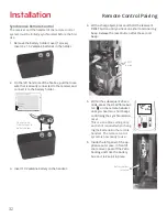
Страница 32: ...hold the receiver s RESET button until you hear one short and one long beep Release the reset button after the second beep 5 Within the subsequent 20 sec onds press the small flame but ton on the remo...

Страница 33: ...fuel bed used altitude and other considerations the flame picture may be improved by adjusting the aeration The need for adjustment should be determined only by operating the appliance with the fuel b...

Страница 34: ...ront Trim and Barrier Screen Install the front or trim chosen by the customer for their fireplace Install as well the barrier screen which is provided with the front or trim Show the customer how to a...

Страница 35: ...ote that the holder can be installed at the base of a light switch plate IMPORTANT The location of the remote control handset is important to assure proper temperature regulation To obtain a constant...

Страница 36: ...LOT MAN Knob Combination Control Valve Main Valve Knob PANEL red yellow Receiver Antenna RESET Button Optional Wall Switch Kit Connector Thermocouple 8 Wire Cable bundled ON OFF Switch Optional 795CFK...

Страница 37: ...TA 4DCAT33 Aluminum Flexible Liner 3 or 4 diameter NOTE 2 ply liner approved to CAN ULC S635 suitable for venting gas appliances As manufactured by Z Flex Flexmaster and others 2280 Series AF3 35L TM...

Страница 38: ...I RX VPHOO JDV 6TOP Follow LQ WKH VDIHW LQIRUPDWLRQ DERYH RQ WKLV ODEHO I RX GRQ W VPHOO JDV JR WR WKH QH W VWep 3 AUTOMA7 1 7 21 J RFDWH WKH SLORW J LQVLGH RI UHER 21 2 VZLWFK LQ 21 SRVLWLRQ 0 1 NQR...

Страница 39: ...hearth SET scrolls through modes and settings OFF returns to set mode turns the burner and WKH SLORW R DUJH DPH EXWWRQ DPHV up sets hours temperature 6PDOO DPH EXWWRQ DPHV GRZQ DQG R VHWV PLQXWHV tem...

Страница 40: ...pilot is lit room temperature is measured and compared to set temperature Flame height automatically adjust to reach Daytime Set Temperature Light Dimmer Mode Not available on this replace Fan Mode T...

Страница 41: ...Press SET to scroll to TEMP Hold SET button until TEMP ashes To set Night Time Temperature increases temperature decreases temperature Press or wait to complete setting Setting Program Timers You can...

Страница 42: ...extended period of time the system automatically extinguishes the pilot This feature helps the consumer realize cost bene ts by automatically eliminating energy consumption during non heating months a...

Страница 43: ...atural gas 9730010 Injector elbow 92 300 propane 9730035 34 Gas supply tube assembly 4007848 35 Thermocurrent interruptor 4001037 36 GV60 Valve assembly natural gas 4007896X GV60 Valve assembly propan...

Страница 44: ...008304 67 Traditional log kit 1000LSKV2 Log no H32 4008905 Log no H33 4008906 Log no H34 4008617 Log no G4 4008162 Log no G10 4008168 Log no H28 4007505 Log no G16 4008306 Log no H31 4007508 Log no H1...

Страница 45: ...45 2 1 3 3 4 6 7 8 9 10 11 12 13 14 15 16 17 18 19 20 23 24 26 27 28 29 30 31 32 33 34 35 36 37 39 40 41 42 43 44 45 46 47 5 25 69 NG Propane Appendix C Spare Parts...

Страница 46: ...61 62 63 64 65 Reflective Glass Rear Panel 66 67 68 Front bricks use front bricks supplied with 780M appliance voir no 8 et 9 Appendix C Spare Parts 1000BLKV2 H15 H36 H17 H20 H21 G15 G4 H22 1000DWKV2...

Отзывы: