background image

5-18

Valco Cincinnati, Inc.

Section 5 - Operation

MC090 - MCP-6 Control Unit

Diagnostic
Button

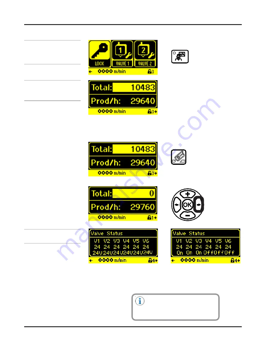
The first diagnostic screen shows the total number of products and the
number of products per hour. The total number of products count can be reset
to zero by pressing the Erase Button.

(All Applications)

The second diagnostic screen shows the valve status.  The top numbers
show the valve type. The bottom numbers will switch back and forth from
showing the valve voltage to showing the valve status (enabled or disabled).

Total Products/

Products per Hour

Valve Status

A voltage reading of 0.0 could
indicate a blown fuse. See Section 8,
Parts List, for fuse numbers and
placement.

Содержание MCP-6

Страница 1: ...MCP 6 Control Unit MCP 6 Control Unit MCP 6 Control Unit MCP 6 Control Unit MCP 6 Control Unit Manual Number MC090 Release Date 8 2017 ...

Страница 2: ...nnati Inc 497 Circle Freeway Drive Suite 490 Cincinnati OH 45246 Tel 513 874 6550 Fax 513 874 3612 Email sales valcomelton com Web http www valcocincinnatiinc com Valco Cincinnati Limited Valco Cincinnati Limited Valco Cincinnati Limited Valco Cincinnati Limited Valco Cincinnati Limited Hortonwood 32 Telford TFI 7YN England Tel 44 1952 677911 Fax 44 1952 677945 Email sales valco co uk Web http www...

Страница 3: ...tonwood 32 Telford TF1 7YN England Melton S L U Pol Industrial Agustinos calle G n 34 31160 Orcoyen Navarra Spain declares that the product Product Name MCP 6 Control Unit complies with the following Council Directives Safety of Machinery 2006 42 EC Low Voltage Equipment 2014 35 EU EM C 2014 30 EU Reduction of Hazardous Substances RoHS 2011 65 EC and conform s to the following standards Safety EN6...

Страница 4: ...ot Adhesive Occurs 2 7 What to Do if Inhalation of Adhesive Fumes Occurs 2 7 What to Do if Adhesive Related Fire or Explosion Occurs 2 8 Hose Safety Information 2 9 Section 3 Basic features 3 1 MCP 6 Control 3 1 Front Panel 3 1 Bottom Panel 3 2 Wiring Diagram 3 3 Mounting Footprint 3 4 Section 4 Programming 4 1 Mounting 4 1 Using the Operator Interface 4 1 The Operator Interface Buttons 4 1 The Ma...

Страница 5: ...n 4 22 Section 5 Operation 5 1 Set the Pattern Menu Information 5 1 Scrolling Through Valve Numbers with the Pattern Button 5 1 Gluing Mode 5 2 Batch Counter 5 3 Scanner Lockout 5 3 Valve to Scanner Distance 5 4 Input Values Gluing Mode 5 5 Set the Pressures 5 11 Pressure Offset Value 5 11 Purge Pressure 5 11 Minimum Speed Pressure 5 12 Maximum Speed Pressure 5 12 Helpful Hints about Pressures 5 1...

Страница 6: ...rt number list 6 1 How to Order Parts 6 1 MCP 6 Control Assembly 074XX056 6 2 Section 7 Specifications 7 1 Section 8 Warranty 8 1 Warranty Information 8 1 Cold Glue Equipment and Electronic Controls 8 1 Hot Melt Units Hoses Valves Guns and Related Equipment 8 1 Section 9 Service 9 1 ...

Страница 7: ...tibility chart Labeler Application Control Description The reason for providing variable time ranges is to extend the performance life of both the glue valves and solenoid valves When the time cycle is set properly all valves remain energized during continuous product flow Upon startup or after a production interruption the valves are energized and de energized per individual container until produ...

Страница 8: ...t melt systems the EPC12 can control the air pressure to an air driven adhesive pump and pneumatic compound relief valves to increase and decrease adhesive pressure related to machine speed EPC12 Capabilities Fluid flow control Fluid flow control Fluid flow control Fluid flow control Fluid flow control The EPC12 changes fluid pressure regulator output in response to parent machine speed changes Th...

Страница 9: ...1 3 Valco Cincinnati Inc Section 1 Introduction MC090 MCP 6 Control Unit EPC12 Capabilities Continued See enlarged view next page ...

Страница 10: ...1 4 Valco Cincinnati Inc Section 1 Introduction MC0090 MCP 6 Control Unit EPC12 Capabilities Continued Enlarged View ...

Страница 11: ...rnings draw special attention to anything that could injure or kill the reader Both Cautions and Warnings are placed before the step they apply to This symbol represents a Hot Surface Hot Surface Hot Surface Hot Surface Hot Surface This symbol represents a Puncture Risk Puncture Risk Puncture Risk Puncture Risk Puncture Risk It is usually used in regard to nozzle cleaning appliances and other shar...

Страница 12: ...ower Unplug Disconnect All Power Sources Sources Sources Sources Sources and to let them de energize before attempting any type of work or maintenance Remember that there can still be energy in equipment cords and wires even when unplugged disconnected This symbol indicates the need to Lock Out All Power Sources Lock Out All Power Sources Lock Out All Power Sources Lock Out All Power Sources Lock ...

Страница 13: ...are regular inspections of equipment and safety devices Have regular safety drills and inspections supervised by the proper authorities Provide all required safety items first aid equipment and training The owner of the equipment is under obligation to make certain that all personnel who will handle install maintain operate fix and work around the equipment are qualified trained and up to date wit...

Страница 14: ...and other power supplies Replace worn cords hoses etc immediately FAILURE TO OBSERVE WARNING MAY RESULT IN DEATH PERSONAL INJURY AND OR EQUIPMENT DAMAGE Warning Warning Warning Warning Warning Poor ventilation smoking and open flames can cause overheated hot melt to ignite Adequate ventilation must be provided Smoking should be prohibited in the immediate vicinity of the molten adhesive Open flame...

Страница 15: ...be energized even if unplugged When making adjustments or performing checkout procedures stay clear of any moving mechanical parts and do not touch exposed electrical equipment or electrical connectors OTHERWISE DEATH OR PERSONAL INJURY COULD OCCUR Warning Warning Warning Warning Warning Disconnect disable all mechanical and or electrical devices that send activation signals to the gun s valve s m...

Страница 16: ...mentioned this is not intended to be an exhaustive list follow all instructions and safety precautions for the specific type of equipment involved Warning Warning Warning Warning Warning Keep pump cover and electrical enclosures closed except during setup service and checkout procedures OTHERWISE DEATH OR PERSONAL INJURY COULD OCCUR Warning Warning Warning Warning Warning People with respiratory p...

Страница 17: ...e of clean cold water be provided near the hot melt work area 2 Cover the affected area with a clean wet compress and call the emergency medical response system such as 911 immediately 3 Watch for and treat the subject for signs of shock while waiting for professional help to arrive What to Do if Contact with Hot Adhesive Occurs If adhesive fumes are inhaled immediately follow these steps 1 Take t...

Страница 18: ...he surface of the adhesive will be exposed to air The mixture of polymer fumes and air can catch fire if the hot melt is overheated Warning Warning Warning Warning Warning Poor ventilation smoking and open flames can cause overheated hot melt to ignite Adequate ventilation must be provided Smoking should be prohibited in the immediate vicinity of the molten adhesive Open flames must be kept away f...

Страница 19: ...o not Do not allow kinks or indentations in the hoses Do Do Do Do Do use a minimum bend radius of 10 inches for a 20 inch diameter coil hose Do not Do not Do not Do not Do not use unapproved hooks to hang hoses Do not Do not Do not Do not Do not wrap hoses over or around objects Do Do Do Do Do use a hose hanging kit P N 781xx827 Do not Do not Do not Do not Do not use the one handed one wrench tech...

Страница 20: ...harp edges or points Do Do Do Do Do wrap the hoses in approved padding P N 795xx549 if the hoses must be installed where they will come into contact with objects Do not Do not Do not Do not Do not use worn damaged or bent hoses Do Do Do Do Do inspect all hoses regularly for damage and or wear and replace damaged or worn hoses immediately Hose Safety Information Continued ...

Страница 21: ...ASIC FEATURES MCP 6 Control Front Panel Figure 3 1 MCP 6 Operator Panel LCD Display Right Arrow Button Plus Button Minus Button Erase Button Diagnostics Button Pressure Button Setup Button Job Storage Recall Button Left Arrow Button Valve Enable Buttons 1 6 Purge Button Scanner Status LED Display Valve Status LED Display Pattern Button ...

Страница 22: ...o Cincinnati Inc Section 3 Basic Features MC090 MCP 6 Control Unit Bottom Panel Figure 3 2 MCP 6 Bottom View Valve Outputs or Scanner Inputs as determined by the customer 120 240 VAC Encoder Input 0 10V Output ...

Страница 23: ...TE ENCODER INPUT SHIELD 1 2 3 4 24V NPN PNP GND 1 2 3 4 24 VDC VALVE 24 VDC ENCODER RED 24V A A GND 1 2 3 4 ORANGE GREEN BLACK VALVE 1 6 OUTPUTS ENCODER INPUT SCANNER INPUTS 1 4 POWER AND COMMUNICATION CONNECTOR SAFETY STOP CONNECTOR RS232 DIAGNOSTIC 0 10V OUTPUT EPC OUTPUT 0 10VDC EPC BRN OUT GND GND 1 2 3 4 BLK WHT BLU AIR IN AIR OUT SAFETY STOP 1 2 NOTE JUMPER 1 2 IF NOT USED NOTE ISOLATE UNUSE...

Страница 24: ...3 4 Valco Cincinnati Inc Section 3 Basic Features MC090 MCP 6 Control Unit Mounting Footprint Figure 3 4 MCP 6 Mounting Footprint ...

Страница 25: ...unted on any flat stable surface close to the machine glue station The Operator Interface Buttons can be grouped into four categories see Figure 4 1 Main Menu Buttons Valve Buttons Navigation Buttons Edit Buttons Using the Operator Interface The Operator Interface Buttons Figure 4 1 The Operator Interface Buttons Navigation Buttons Main Menu Buttons Edit Buttons Valve Buttons ...

Страница 26: ... Diagnostics Button allows you to view the MCP 6 Control Unit diagnostics Job Button Pressing the Job Button allows you to save a job and load a job The Main Menu Buttons The Valve Buttons There are 5 Valve Buttons Purge Button Pressing the Purge Button allows you to turn the Manual Purge Mode on and off When the Purge Button LED is on Manual Purge Mode is on In this Mode the Valve Buttons act as ...

Страница 27: ...e 4 2C If this Right Arrow Symbol appears there is an additional menu screen to the right of the current display Press the Right Arrow Button to view the menu screen to the right Left Arrow Button Pressing the Left Arrow Button moves the cursor to the left highlighting each editable field see Figure 4 3A and 4 3B If a Left Arrow Symbol appears in the lower left corner of the screen it indicates th...

Страница 28: ...to decrease the value of the input Erase Button Pressing the Erase Button allows you to return to the factory default settings Holding the Erase Button longer than five seconds will change all pattern settings to 0 OK Button Pressing the OK Button opens and closes the thumbwheel control It also opens highlighted menu screens for editing see example next page Flash Memory Storage The symbol consist...

Страница 29: ...igit Edit When editable information is numerical the information may be edited with the Plus Minus Buttons for single digit editing or the OK Button may be pressed to bring up a thumbwheel for more detailed editing Single Digit Editing Thumbwheel Editing In Thumbwheel Edit use the Right Left Arrow Buttons to select the digit position and the Plus Minus Arrow Buttons to increase decrease the value ...

Страница 30: ...ponding input or output is activated see Figure 4 6 Be sure the encoder scanners valves and the MCP 6 Control Unit have been properly mounted to the parent machine before setting up the control The glue and air lines are not connected until after the control is programmed The Status LEDs Figure 4 6 Status LEDs Scanner Status LED Display Valve Status LED Display ...

Страница 31: ... Buttons for single digit editing Press the Right Arrow Button to Plus Minus Buttons for single digit editing Press the Right Arrow Button to Plus Minus Buttons for single digit editing Press the Right Arrow Button to Plus Minus Buttons for single digit editing Press the Right Arrow Button to Plus Minus Buttons for single digit editing Press the Right Arrow Button to move to the next setup choice ...

Страница 32: ... for closing sealing Core Winding Applying glue to paper stock that is wound to create roll cores for paper towels bathroom tissue etc Timer Mode for controlling regulating product location in system flow Labeler Applying glue to a label to be placed on canned product EPC12 Mode for monitoring air pressure to match glue output to machine speed running a continuous pattern Burn In Test Test functio...

Страница 33: ... changes to take effect Choosing No will return the unit to the previous settings with no changes made All Applications Finished Valve Type Valve Type Valve Type Valve Type Valve Type Valve Type Set the valve type for valves 1 6 If the default valve type that appears is not applicable use the Plus Minus Buttons to scroll through the list of valve types available All Applications ...

Страница 34: ...setup and use the various functions of the MCP 6 Control Unit passwords are used This ensures safety and security of all settings To enter a password do the following Enter password see Thumbwheel vs Single Digit Edit this section Unlocked symbol appears with password level Unlock changes to Lock ...

Страница 35: ...hest user password level At this level the Default password level can be set individual valve settings can be viewed and changed jobs can be saved as well as loaded and the memory can be backed up The Level 2 password can be changed this is explained under the heading Level 2 Password Options Level 3 Service Level 3 Service Level 3 Service Level 3 Service Level 3 Service This password level is res...

Страница 36: ...4 12 Valco Cincinnati Inc Section 4 Programming MC090 MCP 6 Control Unit Protected Level Mode Continued The locked icon appears indicating the unit is in Protected Level Mode Level 0 ...

Страница 37: ...Buttons to move from digit to digit To cancel without changing the password be sure the current be sure the current be sure the current be sure the current be sure the current password showing is correct password showing is correct password showing is correct password showing is correct password showing is correct and only after this confirmation press the OK Button The old password used to enter ...

Страница 38: ...l is set at Level 1 this screen appears If the Default Level is set at Level 0 this screen appears The unit is now locked to the Set Default Level see above The new password saved for Level 2 access is required to unlock the system for Level 2 access see the heading Enter Password in this section If the new Level 2 password is forgotten you may call Valco Cincinnati Inc Technical Service for assis...

Страница 39: ...nician and or have assistance from a member of the Valco Technical Assistance Team Caution Caution Caution Caution Caution Changing settings may bring unwanted consequences in the performance of your system Valco Cincinnati Inc recommends having a qualified technician setup your system parameters Otherwise loss of production time may result from improper settings All screens for configuring the va...

Страница 40: ...f Compensation Time Toff Off Compensation Time Toff Off Compensation Time Toff This is the amount of time in milliseconds from when the valve is turned off to when the adhesive application is stopped Increasing the Off compensation time will make the glue line shorter Minimum Compensation Time Tmin Minimum Compensation Time Tmin Minimum Compensation Time Tmin Minimum Compensation Time Tmin Minimum...

Страница 41: ... This feature is used on right angle machines when the valves are mounted in sections that are running at different speeds To be as precise as possible the encoder should always be mounted in the section that is running the fastest Minimum Product Length Minimum Product Length Minimum Product Length Minimum Product Length Minimum Product Length The length of a product that is necessary to trigger ...

Страница 42: ...at all screens will appear in the chosen language All Applications Use the Plus Minus Buttons to scroll through all available choices Make sure the desired choice is highlighted on the screen before moving to the next parameter setting To move though the parameter screens use the Right Left Buttons Some parameter screens that appeared in the Wizard may also appear in the Setup Button Menu x2 x2 x2...

Страница 43: ...rom the leading edge of the product see Section 5 Operation This Mode requires an encoder and is not available for Timer applications Pattern Entry Mode Delay Length Mode Delay Length Mode Delay Length Mode Delay Length Mode Delay Length Mode There is a delay length from the leading edge of the product to the start of the glue line These measurements and the length of the glue line will be input d...

Страница 44: ...iguration Valves Output Configuration Valves Output Configuration Valves Output Configuration Valves Set the number of valves being used Up to four valves channels are available Output Configuration Transducer Output Configuration Transducer Output Configuration Transducer Output Configuration Transducer Output Configuration Transducer Set the number of transducers being used Currently there is on...

Страница 45: ... Patterns Menu Configuration Maximum Patterns Set the number of patterns being used Up to ten patterns are available Menu Configuration Maximum Pressure Points Menu Configuration Maximum Pressure Points Menu Configuration Maximum Pressure Points Menu Configuration Maximum Pressure Points Menu Configuration Maximum Pressure Points Set the number of pressure points being used from two to four Menu C...

Страница 46: ... x2 x2 x2 Speed Calculation Immediate Average Speed Calculation Immediate Average Speed Calculation Immediate Average Speed Calculation Immediate Average Speed Calculation Immediate Average Average is the default setting and will work for the majority of jobs However if an immediate reaction to a change of the encoder speed is needed the setting should be changed to Immediate Speed Calculation Red...

Страница 47: ...ens are hidden To edit the highlighted value press the OK Button for the thumbwheel or press the Plus Minus Buttons for single digit editing see Section 4 Programming Thumbwheel vs Single Digit Edit The default screen always shows valve 1 Before entering any data it is advisable to check the left side of the screen for the valve number Make certain the desired valve number appears before entering ...

Страница 48: ...hesive continuously when speed is higher than the Vmin setting 2 Stitch Stitch Stitch Stitch Stitch Applies adhesive in a stitch like pattern Gluing Mode Glue Mode Glue Mode Glue Mode Glue Mode Glue Mode The gluing style Use the Plus Minus Buttons to scroll through the choices These are depending on the application chosen 1 Pattern Pattern Pattern Pattern Pattern Adhesive is applied in a pattern o...

Страница 49: ... with the switch using the Plus Minus Buttons Batch Counter Skip Batch Counter Skip Batch Counter Skip Batch Counter Skip Batch Counter Skip The total number of products for which the pattern will be skipped no adhesive will be applied Batch Counter Glue Batch Counter Glue Batch Counter Glue Batch Counter Glue Batch Counter Glue The total number of products the adhesive pattern will be applied to ...

Страница 50: ...n to the scanner number shown in the upper right corner see Valve to Scanner Distance Scanner Number above Valve to Scanner Distance Scanner Number Valve to Scanner Distance Scanner Number Valve to Scanner Distance Scanner Number Valve to Scanner Distance Scanner Number Valve to Scanner Distance Scanner Number The number of the assigned scanner To choose a scanner press the Plus Button until the d...

Страница 51: ...uto Glue Auto Glue Auto Glue Auto Glue Packaging and Others Pattern Mode Pattern Mode Pattern Mode Pattern Mode Pattern Mode Timer Core Winding and Others Stitch Stitch Stitch Stitch Stitch Others The screens above are unique to each gluing mode Each screen is designed to show comprehensive information at a glance The following subsection Glue Mode Screen Information explains how ...

Страница 52: ...ght Arrow Button to view the Pattern Length for pattern 1 The Pattern Length is the length of the glue line for the pattern number indicated Press the OK Button to view the thumbwheel and use the Plus Minus Buttons to change Press the OK Button to enter the setting Pattern Mode Example Pattern Mode Example Pattern Mode Example Pattern Mode Example Pattern Mode Example Valve Number 1 4 Pattern Numb...

Страница 53: ...his number can be adjusted if desired Pattern Mode Example Continued 4 Press the Right Arrow Button to view the Pattern Length for pattern 2 Press the OK Button to view the thumbwheel and use the Plus Minus Buttons to change Press the OK Button to enter the setting Pattern 2 highlighted active Delay Length for Pattern 2 automatically filled in Previous Pattern Pattern 1 Pattern Length for Pattern ...

Страница 54: ... 7 All three patterns are now set To review them use the Left Arrow Button 8 Use the Left and Right Arrow Buttons to review all information as desired All three patterns have been set and the Pattern Glue Mode for Valve 1 is now ready Pattern 2 highlighted active Previous Pattern Pattern 1 Next Pattern Pattern 3 Notice this screen shows pattern 3 to the right of pattern 2 confirming that there is ...

Страница 55: ...ode is very similar to Pattern Mode with the exception that the glue patterns are applied in a stitch like pattern Machine Speed Password Security Level Pattern Number Up to ten patterns are available The number of patterns available dependontheMenu Configuration settings see Section 4 Programming Delay Length For the Pattern Number shown ST Stitch Mode Valve Number 1 4 Indicates a menu screen to ...

Страница 56: ...y Length End Delay Length the end of the glue line to the trailing edge of the product are entered The glue is applied automatically based on the length of the scanner signal Valve Number 1 4 Start Delay Length Machine Speed Indicates a menu screen to the Left Press the Left Arrow Button to see it Password Security Level End Delay Length Auto Auto Glue Mode Auto Glue Mode Menus Auto Glue Mode Menu...

Страница 57: ...e Offset Value Pressure Offset Value Pressure Offset Value Pressure Offset Value Used to increase decrease the current pressure The Pressure Offset is used to do minor pressure adjustments instantly It does not change the pressure table profile Pressure Offset Value Purge Pressure All Applications Purge Pressure Purge Pressure Purge Pressure Purge Pressure Purge Pressure The pressure setting when ...

Страница 58: ...spectively These pressure points are set up just like the Maximum and Minimum Pressures Pressure Point 1 PT1 Pressure Point 2 PT2 All Applications All Applications Press the Left Right Buttons as indicated by Left Right Arrow Icons on the bottom of the screen see example at left to see all available pressure setting menus The number of pressure points on the pressure curve are input during setup S...

Страница 59: ...t speed setting the third speed setting can never be less than the second speed setting and so on Therefore if you cannot set speeds to where you want them the Plus Minus Arrow Buttons will not increase or decrease the setting check all four of the settings Use the Left Arrow and Right Arrow Buttons to move through all pressures speeds and check them Reset them as necessary using the Plus Minus Ar...

Страница 60: ...ach channel is preconfigured to use MAC24 valves To change this option see Section 4 Programming First Use Setup Wizard Valve Type Basic Startup Parameters to Change Basic Startup Parameters to Change Basic Startup Parameters to Change Basic Startup Parameters to Change Basic Startup Parameters to Change Pattern Screen Pattern Screen Pattern Screen Pattern Screen Pattern Screen The delay time must...

Страница 61: ...er second EXAMPLE Assuming a production run of 240 pieces per minute Step 1 240 pcs min 4 pcs sec 60 sec Step 2 _____1_____ 25 seconds 4 pcs sec Presetting to a setup that corresponds to production flow is possible but not mandatory The operator needs only know what the anticipated flow rate is in pieces per minute to compute the proper setting The following formula and example shows how to make t...

Страница 62: ... setup Valve setup Valve setup Valves 1 6 are preset to Continuous mode so that only that pattern screen will be visible 1 For each valve under the settings menu set the speed threshold The speed threshold is defaulted to 3 ft min This means the valve will only activate when the machine speed is greater than 3 ft per min By default the external Enable signal is set to Scanner 4 under the System Se...

Страница 63: ...5 17 Valco Cincinnati Inc Section 5 Operation MC090 MCP 6 Control Unit b Press the Right Arrow key to access the desired menu EPC12 Application Continued ...

Страница 64: ...e reset to zero by pressing the Erase Button All Applications The second diagnostic screen shows the valve status The top numbers show the valve type The bottom numbers will switch back and forth from showing the valve voltage to showing the valve status enabled or disabled Total Products Products per Hour Valve Status A voltage reading of 0 0 could indicate a blown fuse See Section 8 Parts List f...

Страница 65: ...plays the scanner and trigger settings The event history screen displays error messages The number of pulses per product length This number is helpful in setting up the Ratio Compensation Control Information The control information screen displays application APP and Hard Drive Disk HDD information HDD indicates How much storage for the Job is left in the Flash Memory higher number at left and How...

Страница 66: ... job When Load is highlighted press the OK Button to enter a job number Use the Plus Minus Buttons to change the job number When the desired job number has been entered press the Right Arrow Button to highlight OK and press the OK Button The job is loaded Enter the job number and information in a chart see Appendix A Job Charts for quick job set up Also jobs can be overwritten so it is important t...

Страница 67: ...r Press the Right Arrow Button to highlight Save and then press the OK Button Use the Plus Minus Buttons to change the job number Press the Right Arrow Button to highlight OK Press the OK Button to save the job Be sure to write the job name and job number for reference see Appendix A Job Charts Only password levels 2 or higher can save a job ...

Страница 68: ... Valco Cincinnati Limited Valco Cincinnati Limited Valco Cincinnati Limited Hortonwood 32 Telford TFI 7YN England Tel 44 1952 677911 Fax 44 1952 677945 Email sales valco co uk Web http www valco co uk Valco Cincinnati GmbH Valco Cincinnati GmbH Valco Cincinnati GmbH Valco Cincinnati GmbH Valco Cincinnati GmbH Bonnerstrasse 349 40589 Dusseldorf Benrath Germany Tel 49 211 984 798 0 Fax 49 211 984 79...

Страница 69: ...84XX219 9 11 PCB ASSY PCM6 VALVE 151XX691 1 12 PCB ASSY VALVE DRIVER TOP HM 151XX672 1 13 HOLE PLUG 781XX228 10 14 STANDOFF 091XX545 8 15 WASHER 798XX382 4 16 SCREW 798XX188 4 17 MOUNTING PLATE DISPLAY 026XX322 1 18 SCREW 784XX112 9 19 SCREW 884XX288 6 20 SCREW 784XX047 4 21 SCREW 798XX192 4 22 FLAT WASHER 784XX183 8 23 LOCK NUT 784XX441 4 24 CABLE ASSY PAT CONR COSEL MCP6 029XX605 1 25 CABLE ASSY...

Страница 70: ...ATIONS SECTION 7 SPECIFICATIONS SECTION 7 SPECIFICATIONS SECTION 7 SPECIFICATIONS Height 233 7 mm Width 297 4 mm Depth 157 5 mm Valve Capacity Six 6 valves Input 90 240 VAC Output 24 VDC Maximum Wattage per channel 20W Maximum Wattage Total of ALL channels 100W ...

Страница 71: ...r s warranty In no event shall Valco Cincinnati Inc be liable for indirect or consequential damages arising out of the use of Valco Cincinnati products This warranty is conditioned upon the prepaid return of the equipment claimed to be defective to Valco Cincinnati Inc for examination and verification If claimed defect is verified repairs or replacements will be made F O B Cincinnati Ohio U S A or...

Страница 72: ...ice call will be quoted at that time Any part that fails during the warranty period shall be returned prepaid to Valco Cincinnati Inc by the customer for disposition Upon request ValcoMelton personnel are available to repair or replace such parts at the customer s facility Charges for this service include travel time and expenses If an equipment problem is the result of customer abuse improper ins...

Отзывы: