background image

5. Troubleshooting

5.1 Problem Situations

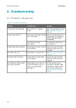
Table 10 Troubleshooting Table

Problem

Possible Cause

Solution

Green status LED is flashing.

DGA monitor is in standby
mode.

Start the measurement mode.
See 

Starting Measurement

(page 30)

.

Yellow status LED is lit.

DGA monitor has been installed
but not initialized.

Perform commissioning and
initialization according to the

OPT100 Installation Guide
(M211857EN)

.

DGA monitor has been
uninstalled.

Confirm the cause from the
user interface.

Yellow status LED is flashing.

Gas level alert is active, caution
limit exceeded.

Log in to the user interface.
Check gas levels and active
messages.

Red status LED is lit.

DGA monitor is in error state.

See 

Resolving a Device Error

(page 51)

.

Red status LED is flashing.

Gas level alert is active, alarm
limit exceeded.

Log in to the user interface.
Check gas levels and active
messages.

Data missing in measurement
view (gaps in graphs)

Measurement cycles have not
produced reliable results for
some or all measurement
parameters

Can be caused by rapid
temperature changes. Make
sure the DGA monitor doors
are closed and locked. See

Notes for Normal Operation
(page 9)

.

OPT100 User Guide

M211858EN-E

50

Содержание Optimus OPT100

Страница 1: ...M211858EN E User Guide Vaisala Optimus DGA Monitor for Transformers OPT100...

Страница 2: ...y given time and hereby disclaims any and all responsibilities related thereto This document does not create any legally binding obligations for Vaisala towards customers or end users All legally bind...

Страница 3: ...17 2 11 Modbus Protocol 17 2 12 DNP3 Protocol 18 2 13 IEC 61850 Protocol 18 3 User Interface 19 3 1 Overview of User Interface 19 3 1 1 Connecting to User Interface 19 3 1 2 Measurements Page 21 3 1 3...

Страница 4: ...DGA Monitor 47 5 Troubleshooting 50 5 1 Problem Situations 50 5 2 Resolving a Device Error 51 6 Technical Data 53 6 1 OPT100 Technical Specification 53 6 2 OPT100 Spare Parts and Accessories 58 6 3 OP...

Страница 5: ...alues 22 Figure 12 Table of Latest Values 23 Figure 13 Duval Triangles on the DGA Diagnostics Page 24 Figure 14 Alerts Page 25 Figure 15 Control Page 26 Figure 16 Settings Page 27 Figure 17 About Page...

Страница 6: ...able 11 Measured Parameters in Oil 53 Table 12 Measurement Performance 53 Table 13 Calculated Parameters 54 Table 14 Operating Environment 54 Table 15 Power Supply 55 Table 16 Outputs 55 Table 17 Mech...

Страница 7: ...ving a Device Error page 51 Updated sections Overview of User Interface page 19 Updating DGA Monitor Software page 42 Problem Situations page 50 M211858EN D July 2018 Applicable from software version...

Страница 8: ...be damaged or important data could be lost CAUTION Note highlights important information on using the product Tip gives information for using the product more efficiently Lists tools needed to perform...

Страница 9: ...tors through the browser based user interface More Information OPT100 Technical Specification page 53 2 2 Basic Features and Options Measurement of seven fault gases and moisture in oil Several calcul...

Страница 10: ...f change ROC ppmv Available for single gases and TDCG for 24 h 7 d and 30 d periods Gas ratios for CH4 H2 C2H2 C2H4 C2H2 CH4 C2H6 C2H2 C2H4 C2H6 CO2 CO Ratio Ratio is calculated from 24 h average valu...

Страница 11: ...ion In normal operation the DGA monitor performs measurement cycles automatically without any operator involvement Integration with a SCADA system is recommended for convenient monitoring of measureme...

Страница 12: ...g Set 1 2 3 4 5 6 7 Figure 1 OPT100 Front Parts with Ground Mounting Set 1 Status LEDs 2 OPT100 DGA Monitor 3 Door lock 3 pcs 4 Power supply unit 5 Door lock 6 Mounting stand 7 Wedge anchors 6 pcs OPT...

Страница 13: ...1 2 3 Figure 2 OPT100 Rear Parts with Ground Mounting Set 1 Weather shield 2 Cable glands and oil connections for DGA Monitor 3 Cable glands for power supply unit Chapter 2 Product Overview 11...

Страница 14: ...rts with Wall Mounting Set 1 2 3 4 5 Figure 3 OPT100 Front Parts with Wall Mounting Set 1 Status LEDs 2 OPT100 DGA Monitor 3 Door lock 3 pcs 4 Power supply unit 5 Door lock OPT100 User Guide M211858EN...

Страница 15: ...ar Parts with Wall Mounting Set 1 Installation beam upper 2 Weather shield 3 Installation beam lower 4 Cable glands for DGA Monitor 5 Cradle for power supply unit 6 Cable glands for power supply unit...

Страница 16: ...y control to power supply unit 6 DC in 24 VDC connection from power supply unit 7 Ethernet external RJ45 connector for permanent Ethernet connection 1 2 3 4 5 6 7 Figure 6 OPTPSU1 Power Supply Unit Ca...

Страница 17: ...ture 8 Oil out 9 Oil in 10 Terminal blocks for RS 485 output Y1 and relay control Y2 11 Circuit breakers for DC power main breaker F2 and breaker for heating power F1 12 Terminal block for DC in Y3 13...

Страница 18: ...al block X1 2 9 Status LEDs Figure 9 Status LEDs Table 5 Meaning of Status LEDs Color Meaning Green DGA monitor is operating normally and performing measurement cycles Green flashing DGA monitor is in...

Страница 19: ...has been in the standby state it must complete 3 measurement cycles before alarms can be activated Alerts will not be activated during the first autocalibration after installation A single large jump...

Страница 20: ...protocol is an optional feature and requires a license If a license is not installed on the DGA monitor you cannot enable the protocol Contact Vaisala for acquiring the license Data measured by DGA mo...

Страница 21: ...be used to access the user interface Additionally local access to the interface is provided by direct access to ETH1 port of the processing unit 3 1 1 Connecting to User Interface Laptop computer with...

Страница 22: ...without making changes to the system 4 If logging in as Admin enter the unique admin password for this OPT100 DGA Monitor The password is included in the OPT100 delivery documentation No password is...

Страница 23: ...lecting the parameter set that is shown 5 Parameters that are shown on the left y axis To show and hide parameters select their color tab 6 Time slider for selecting the time window shown in the graph...

Страница 24: ...Figure 11 Measurement Graph for 1 Day Rate of Change Values OPT100 User Guide M211858EN E 22...

Страница 25: ...s DGA method for transformer fault diagnostics purposes Duval Triangles IEC 60599 Annex B Customer acknowledges and agrees that Vaisala shall not assume any risk or liability in connection with the us...

Страница 26: ...s using methane ethylene and ethane DGA monitor automatically selects the data points according to criteria described in section Criteria for Data Points in DGA Diagnostics page 24 The data points are...

Страница 27: ...conditions is true Concentration of all triangle 1 gases is higher than OPT100 accuracy as listed in Table 8 page 25 At least one of the triangle 1 gases is above the limit based on IEC 60599 as list...

Страница 28: ...d automatic acknowledgement is off 3 1 5 Control Page Control page shows the current status of the DGA monitor and contains the controls for initialization starting and stopping the measurement and un...

Страница 29: ...nged by the Admin user Figure 16 Settings Page 3 1 7 About Page About page shows the serial number and software version of the DGA monitor There are also two buttons Update starts the software update...

Страница 30: ...as level is no longer above the limit or until the alert is disabled Flashing yellow or red status LED on the DGA monitor door means that one or more gas level alert and the corresponding message is a...

Страница 31: ...GA monitor is performing autocalibration cycles Autocalibration improves measurement performance by adapting the DGA monitor to transformer oil conditions Autocalibration takes from 2 to 5 days depend...

Страница 32: ...installing DGA monitor is being uninstalled Uninstallation empties the DGA monitor of oil and prepares the measurement system for transportation 3 2 Starting Measurement In normal operation DGA monito...

Страница 33: ...and automatic acknowledgement is off 1 Connect to the user interface as the Admin user See Connecting to User Interface page 19 2 In the user interface select Alerts 3 Configure Automatic acknowledgin...

Страница 34: ...the alert Output protocols do not communicate the alert as active Admin user can acknowledge alarms or enable automatic acknowledging from the Alerts page in the user interface Select Acknowledge aler...

Страница 35: ...Figure 20 Alert Screen with Methane Caution Alert Visible 3 5 Setting Date and Time Figure 21 Date and Time Settings Page Chapter 3 User Interface 33...

Страница 36: ...otation in the form hh mm d Select Apply to save the manually set time 5 To set up time synchronization with a Network Time Protocol NTP server NTP synchronization requires that the network connection...

Страница 37: ...See Connecting to User Interface page 19 2 In the top right corner of the user interface select Admin Change password 3 Enter the current password in the Current password field 4 Enter the new passwo...

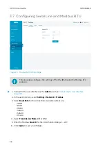
Страница 38: ...interface as the Admin user See Connecting to User Interface page 19 2 In the user interface select Settings Network Modbus 3 Select Baud Rate for the connection Available options are 4800 9600 19200...

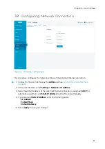
Страница 39: ...ting to User Interface page 19 2 In the user interface select Settings Network IP Address 3 Select how the IP address of the external Ethernet connection is assigned DHCP for automatic assignment and...

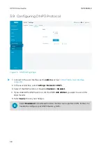
Страница 40: ...lect Settings Network DNP3 3 Select if the DNP3 protocol should be Enabled or Disabled 4 If you enabled the DNP3 protocol set the DNP3 Link Address you want to use on this DGA monitor 5 Select Apply t...

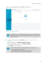
Страница 41: ...o the user interface as the Admin user See Connecting to User Interface page 19 2 In the user interface select Settings Network IEC 61850 3 Select if the IEC 61850 protocol should be Enabled or Disabl...

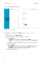
Страница 42: ...ted Trigger In Test mode the relay activation is controlled manually from the Set test state buttons If the relay is not used select the Test mode You can also use it to test that wiring has been conn...

Страница 43: ...DGA monitor that are marked with the symbol below heat up during normal operation Avoid touching hot surfaces and wear protective gloves when working inside the enclosure Whenever possible allow the...

Страница 44: ...mple Modbus If a problem with the DGA monitor is indicated check the user interface 4 4 Updating DGA Monitor Software Software update file for DGA monitor Software update does not delete the data stor...

Страница 45: ...o Standby mode See Stopping Measurement page 45 3 Verify that date and time on the DGA monitor are set correctly See Setting Date and Time page 33 4 Wait for DGA monitor to finish stopping and enter t...

Страница 46: ...asurement See Starting Measurement page 30 11 Optional Start autocalibration manually to make sure any updates to the autocalibration mechanism are applied right away See Starting Autocalibration Manu...

Страница 47: ...n the documentation contact Vaisala for assistance Some repairs can only be performed by a Vaisala representative For any components included inside the OPT100 DGA Monitor or the OPTPSU1 power supply...

Страница 48: ...re no open oil connections All oil handling components are securely attached All oil leaks have been cleaned and wiped clean No oil is visible on the parts or oil connections 4 6 4 Turning On DGA Moni...

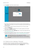
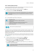
Страница 49: ...GA monitor Uninstallation empties the DGA monitor of oil and allows it to be safely stored and transported When you start the uninstallation oil lines between DGA monitor and transformer must be intac...

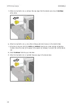
Страница 50: ...alves on the transformer 7 Disconnect oil pipes from the Oil In and Oil Out connections on the outside of the DGA monitor Place the ends of the pipes in the waste oil container to collect the oil that...

Страница 51: ...n off AC power to the DGA monitor a Turn off AC power from the external disconnection device b Lock the disconnection device in the off position if possible c Attach a warning label to the disconnecti...

Страница 52: ...status LED is flashing Gas level alert is active caution limit exceeded Log in to the user interface Check gas levels and active messages Red status LED is lit DGA monitor is in error state See Resolv...

Страница 53: ...the steps below to resolve it 1 Connect to the user interface as the Admin user See Connecting to User Interface page 19 2 Check active messages and status of DGA monitor on the Control page 3 Inspect...

Страница 54: ...page of the user interface you can create a diagnostic data file that can help Vaisala diagnose the device error It is recommended that you do this if your DGA monitor stops due to a device error rega...

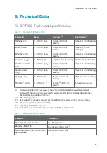
Страница 55: ...r 20 of reading 15 ppm or 10 of reading Moisture 4 H2O 0 100 ppmw 5 2 ppm 6 or 10 of reading Included in accuracy 1 Accuracy specified is the accuracy of the sensors during calibration gas measurement...

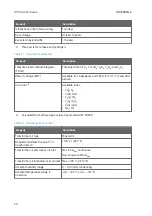
Страница 56: ...30 d periods Gas ratios 1 Available ratios CH4 H2 C2H2 C2H4 C2H2 CH4 C2H6 C2H2 C2H4 C2H6 CO2 CO 1 Calculated from 24 h average values See standard IEC 60599 Table 14 Operating Environment Property De...

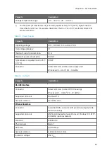
Страница 57: ...at 25 C 77 F 100 W Connector Screw terminals inside power supply unit Wire size 2 5 4 mm2 14 12 AWG Table 16 Outputs Property Description RS 485 Interface Connector Screw terminals inside OPT100 hous...

Страница 58: ...ervice use RJ45 connector inside OPT100 housing temporary local use only Table 17 Mechanical Specifications Property Description Oil fitting Stainless steel Swagelok fitting for 10 mm 0 39 in outer di...

Страница 59: ...als in Contact with Oil Oil pipes chambers and valves Aluminum EN AW 6026 stainless steel AISI 316 brass Gaskets and seals NBR FKM FVMQ Pump gears and bushing PEEK PTFE Table 18 Type Tests Category St...

Страница 60: ...61010 1 2012 CSA C22 2 No 61010 1 12 Compliant Safety requirements for electrical equipment for measurement control and laboratory use Part 1 General requirements Table 19 Compliance Property Descrip...

Страница 61: ...unting Set 1552 61 10 1630 64 17 675 26 57 550 21 65 700 27 56 280 11 02 580 22 83 400 15 75 350 13 78 453 17 83 35 1 38 140 5 51 20 0 79 510 20 08 140 5 51 mm in Figure 30 Dimensions with Ground Moun...

Страница 62: ...ing from one Register addresses in actual Modbus messages Modbus Protocol Data Unit PDU are in hexadecimal and start from zero Subtract 1 from the register number presented in this manual to get the a...

Страница 63: ...or unavailable values A quiet NaN is for example 7FC00000hex however the master should understand any NaN value A complete 32 bit floating point or integer value should be read and written in a single...

Страница 64: ...Saturation Inside Transformer page 8 32 bit float RS 24h Average Values 51 0032hex Methane 32 bit float ppmv 53 0034hex Acetylene 32 bit float ppmv 55 0036hex Ethylene 32 bit float ppmv 57 0038hex Eth...

Страница 65: ...v w 105 0068hex Ethylene 32 bit float ppmv w 107 006Ahex Ethane 32 bit float ppmv w 109 006Chex Carbon monoxide 32 bit float ppmv w 111 006Ehex Carbon dioxide 32 bit float ppmv w 113 0070hex Total dis...

Страница 66: ...nt result set in seconds since start of Unix epoch 64 bit float double s 165 00A4hex Index of measurement result set 32 bit integer A 3 3 Alert Registers Gas level alert registers are 16 bit fields Ea...

Страница 67: ...rbon dioxide 6 TDCG 7 Hydrogen 8 Moisture in oil 9 Relative moisture in oil 12 000Bhex Gas level ROC caution alerts for 24h average values 16 bit field 0 Methane 1 Acetylene 2 Ethylene 3 Ethane 4 Carb...

Страница 68: ...Carbon dioxide 6 TDCG 7 Hydrogen 15 000Ehex Gas level alarms for present values 16 bit field 0 Methane 1 Acetylene 2 Ethylene 3 Ethane 4 Carbon monoxide 5 Carbon dioxide 6 TDCG 7 Hydrogen 8 Moisture...

Страница 69: ...monoxide 5 Carbon dioxide 6 TDCG 7 Hydrogen A 3 4 Test Value Registers Read the known test values from the test registers to verify the functionality of your Modbus implementation Table 25 Test Value...

Страница 70: ...n the same values Request Bytes on the Line Hexadecimal Description silence for 3 5 bytes Start of Modbus RTU frame F0hex OPT100 address 03hex Function Read Holding Registers 00hex Register address Ac...

Страница 71: ...End of Modbus RTU frame Communication Description Register address 23 1 based Modbus documentation format 0016hex 0 based format used in actual communication Data format Two 16 bit Modbus registers in...

Страница 72: ...OPT100 User Guide M211858EN E 70...

Страница 73: ...uring 39 M maintenance remote access 42 software update 42 turning off 45 turning on 46 measured parameters 7 measurement 21 starting 30 47 stopping 45 messages errors 28 gas level alerts 28 Modbus pr...

Страница 74: ...t 30 47 status indicator 29 status LEDs 16 stopping measurement 45 T technical specification 53 troubleshooting 50 turning off 45 turning on 46 U uninstalling 47 user interface 19 about page 27 alerts...

Страница 75: ...e www vaisala com support Warranty For standard warranty terms and conditions see www vaisala com warranty Please observe that any such warranty may not be valid in case of damage due to normal wear a...

Страница 76: ...OPT100 User Guide M211858EN E 74...

Страница 77: ......

Страница 78: ...www vaisala com...

Отзывы: