12
VAIO Operating and installation instructions
5. Installing individual parts
Before installing the wood-burning stove, make sure that all individual parts have been correctly mounted.
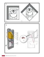
Vertical section of the wood-burning stove (figure B):
1. Baffle plate at the bottom. Should be in contact with the steel rail at the back of the fire compartment.
2. Baffle plate at the top. Should be in contact with the bottom baffle plate.
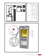
3. The steel baffle plate comes in two parts. Each of the two parts is suspended from a hook on the top
plate and is fitted with a transportation lock in the form of two split pins (7). These two split pins must
be removed before setting the stove into operation.
4. RSmoke outlet at the rear. Connected to a bolted plate in the factory. This means that the exhaust flue
is hidden behind the rear wall.
5. Removable rear wall concealing the automatic system. Should always be mounted when the stove is
installed next to a flammable wall.
6. Loose thermal shield under the ash pan.
Connection to the chimney
The series is fitted with a rear and a top smoke outlet. The stove can be connected at the top or directly at
the rear to a flue.
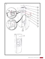
Vertical section in the flue (figure C):
C1: Smoke outlet at the top
C2: Smoke outlet at the rear
1. Steel flue.
2. Elbow pipe. Mount inside the flue pipe connection.
3. Brick-lined chimney.
4. Masonry box. Corresponds to the size of the flue.
5. Wall rose. Conceals repairs in the masonry box area.
6. Connecting point. Seal with sealing strip.
7. VAIO wood-burning stove flues.
8. Cover plate on the external rear wall: Removed in the case of a rear smoke outlet.
9. Bolted cover: Bolted on the top cover plate for a rear smoke outlet.
10. Flue pipe plug-in connector: Bolted on the rear side for a rear smoke outlet.
11. Regulating damper in the flue pipe.
12. Cleaning vent.
13. Flue for rear smoke outlet.
14. Loose cover made of cast iron: Placed on the top cover plate for a rear smoke outlet.
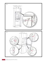
Adjustable feet
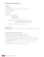
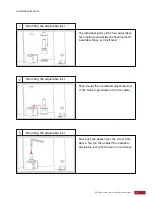
The wood-burning stove’s scope of delivery includes four adjustable feet. Mount the adjustable feet and
adjust the two setting screws on both sides to the required height according to the instructions enclosed.


