background image

0020166663_01 - 07/13 - Vaillant

28

4.4  

 Electrical Installation

e

 Danger!

Risk of electric shock due to an 
improper electrical connection!

Improper electrical connection can cause 
electric shock or might negatively affect the 
operational safety of the product and might 
cause material damage.

• 

The electrical connection of the product 
must be carried out only by a suitably 
qualified person.

1

2

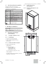
30 mm max.

Key
1 Electrical 

wires

2 Insulation 

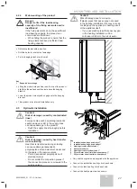
When you connect the electrical wires to a connector on the 

electronic board:


Keep a distance of a maximum of 30 mm between 
connector and the start of the insulation. 


If using single core wires are used ensure that they are 
wrapped together in an insulating sheath.


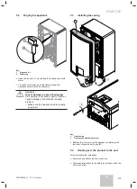
Fix the cables in the cable-clamp on the Box.

4.4.1 

Connecting the power input (mains 
connection)

The external wiring to be grounded. The polarity must be 
correct and consistent with the standards.


Connect the appliance in accordance with the live and 
neutral connections.

The connecting cables between the electrical panel and the 
appliance must be :
- adapted to a fi xed installation,

- resistant to temperatures above 90°C,
- Electrical wires with adapated section linked to the power 
of the appliance.


Connect the device to the electrical panel via an 
independent protection system (circuit breaker with a 
separation of at least 3 mm between each contact).

Additional protection may be required during the installation 
to ensure overvoltage category II.

Switching devices from the mains supply must allow 
complete failure of the supply according to the requirements 
of the overvoltage category III.

Component

Supply voltage

(mini section of cable)

Mono supply 
cable

6 kW

230 V (3 G4)

4 kW

230 V (3 G2.5)

3-phase supply cable

400 V (5 G1.5)

Heating element relay cable  

230 V (3 x 0.75)

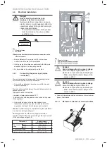
11

2

3

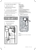
Key
1 Electrical 

casing

230 V electrical connection label

400 V electrical connection label

b

 Caution!

Risk of damage from too great voltage.

At mains voltages higher than 253 V, 
electronic components may be destroyed.

• 

Make sure that the rated voltage of the 
mains is 230 V.

b

 Caution!

Risk of damage from too great voltage.

At mains voltages higher than 440 V, 
electronic components may be destroyed.

• 

Make sure that the rated voltage of the 
mains is 400 V. 


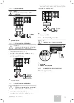
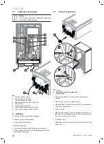
Connect alimentation cables of product on the electrical 
panel of installation.

4.4.1.1 

Method of collection of electrical cables

C

A

B

MOUNTING AND INSTALLATION

Содержание VWZ MEH 61

Страница 1: ...DE GB IT ES VWZ MEH 61 Installationsanleitung und Betriebsanleitung Für den Fachhandwerker und den Betreiber Installationsanleitung und Betriebsanleitung ...

Страница 2: ......

Страница 3: ...Installationsanleitung und Betriebsanleitung DE VWZ MEH 61 DE Installationsanleitung Für den Fachhandwerker Betriebsanleitung Für den Betreiber ...

Страница 4: ...s 8 4 Montage und Installation 8 4 1 Vorbereitung der Montage und Installation 8 4 2 Gerätemontage 9 4 3 Hydraulikinstallation 10 4 4 Elektroinstallation 11 4 5 Kabelführung 13 5 Inbetriebnahme 13 5 1 Füllen des Gerätes 13 5 2 Entlüften des Gerätes 14 5 3 Frontverkleidung montieren 14 5 4 Gerät an den Betreiber übergeben 14 6 Fehlerbehebung 15 6 1 Einzelteile 15 6 2 Gerät entleeren 15 6 3 Rückstel...

Страница 5: ...lge sogar Personenschäden verursachen Führen Sie nur dann Arbeiten am Produkt aus wenn Sie autorisierter Fachhandwerker sind 1 4 Allgemeine Sicherheitshinweise 1 4 1 Lebensgefahr durch Stromschlag Das Berühren von spannungsführenden Anschlüssen kann zu schweren Personenschäden führen Schalten Sie die Stromzufuhr zum Produkt ab bevor Sie Arbeiten durchführen Sichern Sie die Stromzufuhr gegen Wieder...

Страница 6: ...ations und Wartungsanleitungen für dieses Produkt sowie alle weiteren Komponenten der Anlage Die Installation und Montage gemäß der Produkt und Systemzulassung Die Einhaltung aller Inspektions und Wartungsbedingungen aus den Anleitungen Das Gerät muss an einer Stelle installiert werden an der es vor Feuchtigkeit und Spritzwasser geschützt ist Beachten Sie die in den technischen Daten angegebene el...

Страница 7: ...Gerätetypen Produkt Typen bezeichnung Artikelnummer VWZ MEH 61 6 kW 0020143590 3 Produktbeschreibung 3 1 Aufbau des Produktes 3 1 1 Hydraulikstation A B D E F G C 5 8 6 7 1 3 2 4 Legende 1 Ausdehnungsgefäß 2 Sicherheitsventil 3 Drucksensor 4 Temperatursensor 5 Zusatzheizung 6 Entlüftungsventil 7 Entleerungsventil 8 Dreiwegeventil A Rücklauf Heizung B Vorlauf Heizung C Auslauf des Sicherheitsventil...

Страница 8: ...ation i Hinweise Alle in diesem Kapitel dargestellten Abmessungen werden in mm angegeben 4 1 Vorbereitung der Montage und Installation 4 1 1 Lieferung und Installation am Aufstellort 4 1 1 1 Auspacken Nehmen Sie das Gerät aus der Verpackung Entfernen Sie die Schutzfolie von allen Geräteteilen 4 1 1 2 Lieferumfang prüfen Prüfen Sie den Inhalt des Kartons 1 Hydraulikstation 1 Zubehörbeutel Aufhängle...

Страница 9: ...och in einem sehr staubigen Raum oder einer korrosiven Atmosphäre Installieren Sie das Gerät auch nicht unter einem anderen Gerät das undicht sein könnte Stellen Sie sicher dass der Raum in dem das Gerät aufgestellt werden soll hinreichend frostgeschützt ist 4 1 3 2 Beschaffenheit der Montageflächen Bevor Sie den Aufstellort des Geräts wählen lesen Sie bitte die Sicherheitshinweise sowie die Anwei...

Страница 10: ... des elektrischen Moduls Schweißen oder löten Sie die Anschluss tücke nicht wenn diese an den Absper rhähnen angeschraubt sind b Vorsicht Risiko von Sachschäden durch Korrosion Nicht diffusionsdichte Kunststoffrohre in der Heizungsanlage führen zu Lufteintrag in das Heizwasser und zu Korrosion in Wärmeerzeugerkreis und Produkt Nehmen Sie bei Verwendung nicht diffu sionsdichter Kunststoffrohre in d...

Страница 11: ... deren Querschnitt der Leistung des Geräts angepasst ist Schließen Sie die Hydraulikstation über ein unabhängiges Schutzsystem an über eine Unterverteilung mittels eines Fehlerstromschutzschalters mit einer Trennung von mindestens 3 mm zwischen den Kontakten Während der Installation kann ein zusätzlicher Schutz erforderlich sein um der Überspannungskategorie II gerecht zu werden Die Vorrichtungen ...

Страница 12: ...1 Schutz mini 20A 4 4 1 3 Anschluss 400V b Vorsicht Beachten Sie die Angaben auf dem Anschlussplan auf dem Schaltschrank b Vorsicht Beim Anschließen an 400V müssen Sie die Brücken entfernen 02 01 N 1 2 L1 L2 N1 L3 N 400 Smin 5G1 5 L L L 3 2 1 1 Legende 1 Schutz mini 10A 4 4 1 4 Anschluss Steuerrelais i Hinweis Das Gerät wird bereits verkabelt geliefert N N 1 2 L2 L1 L3 1 2 4kW 2kW Legende 1 Steuer...

Страница 13: ... Sie die Stromversorgung des Gerätes wieder her Für den Umgang der Bedieneinheit und die Parametrierung der Hydraulikstation beziehen Sie sich bitte auf die Benutzer und Installationsanleitungen der Wärmepumpe aroTHERM 5 1 Füllen des Gerätes 1 2 3 B A Legende 1 Füllset 2 Zwischenposition 2 Wege offen 3 Ausgangsstellung Schließen Sie das Füllset 1 an einem der Eingänge Ausgänge des Moduls an Schlie...

Страница 14: ...en bei unsachgemäßer Entlüftung Bei unsachgemäßer Entlüftung kann der elektrische Widerstand beschädigt werden Vergewissern Sie sich dass der Heizkreislauf korrekt entlüftet wird 5 3 Frontverkleidung montieren 1 A B 2 Legende 1 Frontverkleidung 2 Befestigungsschraube der Frontverkleidung Bringen Sie die Frontverkleidung des Gerätes wieder an und beachten Sie hierbei die angegebene Reihenfolge der ...

Страница 15: ...ng des elektrischen Widerstands Ein anormaler Anstieg der Wassertemperatur kann das Sicherheitsthermostat des elektrischen Widerstands ausgelösen Die Rückstellung erfolgt manuell i Hinweise Lassen Sie den Widerstand abkühlen bevor Sie ihn wieder einschalten 1 Legende 1 Rückstelltaste Drücken Sie die Rückstelltaste 1 6 4 Überprüfung der Dichtigkeit Überprüfen Sie die Dichtigkeit der Hydraulikkreisl...

Страница 16: ...und Verwertung gesammelter Elektro und Elektronik Altgeräte Entsorgen Sie das Produkt und sein Zubehör nicht im Hausmüll Vergewissern Sie sich dass das Gerät und mögliche Zubehörteile sachgemäß entsorgt werden Geben Sie das Gerät bei einer Sammelstelle ab die für Verarbeitung Verwertung und Recycling von Elektro und Elektronik Altgeräten zugelassen ist Beachten Sie alle geltenden Vorschriften i Hi...

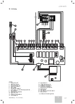
Страница 17: ...ler VF1 2 Kabel Drucksensor 3 Stecker Drucksensor 4 Stecker Vorlauffühler 5 EVU Kontakt 6 Multifunktionseingang 7 DCF Emphänger mit Außentemperaturfühler 8 Speicherfühler 9 Vorlauffühler unbenutzt 10 Regler VRC 470 11 Klemmen Zusatzheizung 12 Zusatzheizgerät 13 Umschaltventil 14 3 Wege Umschaltventil 15 Multifunktionsausgang 2 16 Multifunktionsausgang 1 17 Netzanschluss Alternativ 18 Netzanschluss...

Страница 18: ......

Страница 19: ...Installation instructions and instructions for use EN VWZ MEH 61 Installation instructions For the competent person EN Instructions for use For the operator ...

Страница 20: ...ounting and installation 25 4 1 Preparing the mounting and installation 25 4 2 Mounting the product 26 4 3 Hydraulic installation 27 4 4 Electrical Installation 28 4 5 Cableway and passage 30 5 Start up 30 5 1 Filling the appliance 30 5 2 Purging the appliance 31 5 3 Installing the casing 31 5 4 Handing over the product to the user 31 6 Repair work 32 6 1 Spare parts 32 6 2 Draining the product 32...

Страница 21: ...r to life by electric shock Touching live connections can cause serious personal injury Before carrying out any work on the product switch off the power supply Secure the power supply against being switched on again 1 4 2 Danger to life due to missing or not properly working safety devices Missing safety devices can cause life threatening scalding and other injuries for example by burst pipes The ...

Страница 22: ...it for their purpose and of suitable quality and workmanship The installation of this heating appliance must be carried out by a competent person approved at the time by the Health and Safety Executive and in accordance with the rules in force in the countries of destination Manufacturer s instructions must not be taken as overriding statutory requirements 1 6 5 2 Statutory Requirements In GB the ...

Страница 23: ...0Hz supply Connection of the whole electrical system of the heating appliance including any heating controls to the electrical supply MUST be through one common isolator and must be fused 30 Amp maximum Isolation should be by a double pole switched fused spur box with a minimum gap of 3mm for both poles The fused spur box should be readily accessible and preferably adjacent to the appliance It sho...

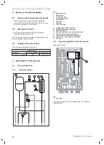
Страница 24: ...le number Electric back up heater 6 kW 0020143590 3 Description of the product 3 1 Product structure 3 1 1 Hydraulic station A B D E F G C 5 8 6 7 1 3 2 4 Key 1 Expansion tank 2 Safety valve 3 Pressure sensor 4 Temperature sensor 5 Electric heater 6 Air bleed 7 Drain tap 8 Three way valve A Installation heating circuit inlet B Installation heating circuit outlet C Safety valve drain D Domestic hot...

Страница 25: ...r CE label See chapter Recycling 4 Mounting and installation i Notes All the drawings dimensions are shown in mm 4 1 Preparing the mounting and installation 4 1 1 Delivery and installation on site 4 1 1 1 product unpack Remove the product from its box Remove the protective film from all parts of the product 4 1 1 2 Vérification du matériel livré Please check the scope of delivery for completeness ...

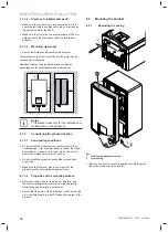
Страница 26: ...3 1 Surrounding conditions Do not install the product above another product that could damage it for example above a cooker that might emit steam or grease or in a room which has a lot of dust in the atmosphere which is corrosive Do not install the product under another product that might leak Make sure that the room where you want to fit the product is sufficiently protected against frost 4 1 3 2...

Страница 27: ... installation b Caution Risk of damage caused by heat transfer when soldering Heat that is transferred during soldering can cause damage expanded polypropylene around electrical modul and to the seals in the service valves Protect expanded polypropylene of electrical modul Do not solder the connection pieces if the connection pieces are screwed to the service valves b Caution Risk of damage due to...

Страница 28: ...emperatures above 90 C Electrical wires with adapated section linked to the power of the appliance Connect the device to the electrical panel via an independent protection system circuit breaker with a separation of at least 3 mm between each contact Additional protection may be required during the installation to ensure overvoltage category II Switching devices from the mains supply must allow co...

Страница 29: ... L L N L Protection mini 30A 3G4 3 2 1 Protection mini 30A Smin 3G4 Key 1 Protection mini 30A 4 4 2 230 V connection 4 kW wiring b Caution Comply with the instructions on the label affixed inside the electrical casing Remove the installed cable 5 G 1 5 Install the 2 shunts as shown on the diagram below Install the supplied 230V cable 02 01 N 1 2 L1 L2 N1 L3 L L N L 3 2 1 Smin 3G2 5 1 Key 1 Protect...

Страница 30: ...em Replace the power To use the AI interface and configure the hydraulic station refer to the user and installer documents for the aroTHERM heat pump 5 1 Filling the appliance 1 2 3 B A Key 1 Filler kit 2 Intermediate position 2 paths open 3 Initial position Connect the filler kit 1 to one of the module inputs outputs Connect the kit tap to the water source Manually place the three way valve into ...

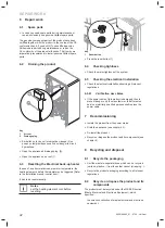
Страница 31: ...ing is not done properly this may cause damage to the electrical heating element Make sure the heating circuit is properly purged air 5 3 Installing the casing 1 A B 2 Key 1 Front casing 2 Front façade attachment screw Replace the front cover of the appliance complying with the order of operations A and B 5 4 Handing over the product to the user After completing the installation Answer any questio...

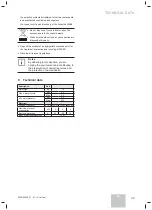
Страница 32: ... to be reset manually i Notes Let the heating element cool before resetting 1 Key 1 Reset button Press the reset button 1 6 4 Checking tightness Check the water tightness of the system 6 5 Checking the electrical installation Check the electrical installation observing all relevant regulations 6 5 4 1 Vérification des câbles If the power cable of this product is damaged then to prevent danger only...

Страница 33: ...ate collection point for the treatment evaluation and recycling of WEEE Observe all relevant regulations i Notes By adhering to this directive you are helping the environment and contributing to the preservation of natural resources and the protection of human health 9 Technical data Description Unit Net Weight kg 10 Max water pressure bar 3 0 Mpa 0 3 Min water pressure bar 0 5 Mpa 0 05 Electrical...

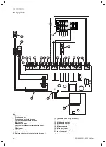
Страница 34: ...ure sensor wiring harness 4 Temperature sensor wiring harness 5 EVU contact 6 Multifunction input 7 DCF receiver with external temperature sensor 8 Cylinder sensor 9 Flow sensor 10 VRC 470 controller 11 Resistance heater box 12 Resistance heater relay control wiring harness 13 Three way valve wiring harness 14 Three way valve 15 Multifunction output 2 16 Multifunction output 1 17 Mains connection ...

Страница 35: ......

Страница 36: ......

Страница 37: ...Istruzioni per l installazione e manuale di servizio IT VWZ MEH 61 IT Istruzioni per l installazione Per il tecnico abilitato Manuale di servizio Per il gestore ...

Страница 38: ...lacca segnaletica 43 4 Montaggio e installazione 43 4 1 Preparazione del montaggio e dell installazione 43 4 2 Montaggio dell apparecchio 44 4 3 Impianto idraulico 45 4 4 Installazione elettriche 46 4 5 Passaggio dei cavi 48 5 Messa in servizio 48 5 1 Riempimento dell apparecchio 49 5 2 Spurgo dell apparecchio 49 5 3 Installazione della parte frontale 50 5 4 Informazioni per l utente 50 6 Manutenz...

Страница 39: ...l prodotto solo se si è un tecnico qualificato 1 4 Norme generali di sicurezza 1 4 1 Pericolo di morte per folgorazione Toccare i collegamenti elettrici in tensione può provocare gravi ferite corporee Prima di effettuare un qualsiasi intervento sull apparecchio togliere la corrente elettrica Verificare che non sia possibile ripristinare l alimentazione elettrica 1 4 2 Pericolo di morte se i dispos...

Страница 40: ...in conformità dell insieme delle condizioni di ispezione e di manutenzione elencate nel presente manuale Bisognerà installare l apparecchio in un luogo in cui non sia esposto all umidità o a spruzzi d acqua Rispettare l indice di protezione elettrica IP che compare nei dati tecnici Qualsiasi altro utilizzo diverso da quello descritto nel presente manuale o che ne allarghi l uso qui descritto non è...

Страница 41: ...relativa alla compatibilità elettromagnetica Direttiva europea n 2006 95 del Parlamento Europeo e del Consiglio relativa alla bassa tensione Direttiva relativa alle apparecchiature di telecomunicazione direttiva R TTE 99 5 CEE del Consiglio della Comunità Europea Direttiva Rendimenti 92 42 CE Direttiva Rendimento Energetico negli edifici 2002 91 CE 0020166663_01 07 13 Vaillant 41 IT SICUREZZA ...

Страница 42: ...ell apparecchio 3 1 Struttura dell apparecchio 3 1 1 Stazione idraulica A B D E F G C 5 8 6 7 1 3 2 4 Legenda 1 Vaso d espansione 2 Valvola di sicurezza 3 Sensore di pressione 4 Sensore di temperatura 5 Resistenza elettrica 6 Disaeratore 7 Rubinetto di scarico 8 Valvola tre vie A Arrivo circuito riscaldamento dall impianto B Mandata circuito riscaldamento verso l impianto C Scarico della valvola d...

Страница 43: ...capitolo Riciclaggio 4 Montaggio e installazione i Note Tutte le misure di questo capitolo sono espresse in mm 4 1 Preparazione del montaggio e dell installazione 4 1 1 Consegna e installazione in loco 4 1 1 1 Disimballaggio Togliere l apparecchio dall imballaggio Togliere la pellicola protettiva da tuti i pezzi dell apparecchio 4 1 1 2 Verifica del materiale consegnato Verificare il contenuto del...

Страница 44: ... da cui potrebbero fuoriuscire dei vapori e del grasso o in un ambiente molto impolverato o con un atmosfera corrosiva Assicurarsi che l ambiente in cui si vuole installare l apparecchio sia sufficientemente protetta dal gelo 4 1 3 2 Pulizia delle superfici di montaggio Prima di scegliere il luogo di installazione dell apparecchio leggere attentamente le indicazioni relative alla sicurezza e le is...

Страница 45: ...i arresto Proteggere il polipropilene espanso del modulo idraulico Non saldare i pezzi dei collegamenti se sono avvitati ai rubinetti di arresto b Attenzione Rischio di danni dovuti alla corrosione Se vengono utilizzate delle tubature di plastica non a tenuta d ossigeno nell impianto di riscaldamento questo può corrodere o ostruire il circuito di riscaldamento e l apparecchio stesso Se si usano de...

Страница 46: ... ciascun contatto Può essere richiesta una protezione supplementare al momento dell installazione per assicurare una categoria di sovratensione II Dispositivi di commutazione dalla rete deve consentire completo fallimento della fornitura secondo i requisiti della categoria di sovratensione III Componente Tensione di alimentazione Sezione cavo mini Cavo di alimentazione monofase 6 kW 230 V 3 G4 4 k...

Страница 47: ...iere il cavo installato 5 G 1 5 Posizionare i 2 shunt come indicato nello schema sottostante Installare il cavo 230 V in dotazione 02 01 N 1 2 L1 L2 N1 L3 L L N L 3 2 1 3G4 Smin 3G4 1 Legenda 1 Protezione mini 30A 4 4 1 4 Raccordo 230 V cablaggio 4 kW b Attenzione Rispettare le indicazioni dell etichetta presente sul quadro elettrico Togliere il cavo installato 5 G 1 5 Posizionare i 2 shunt come i...

Страница 48: ...no passare nei fori previsti a tale scopo 3 4 2 1 8 5 7 5 6 5 7 8 Legenda 1 Cavo sensore di pressione 2 Cavo sensore di temperatura 3 Cavo alimentazione scheda 4 Cavo comando relé resistenza 5 Cavo di alimentazione 6 Cavo motore V3V 7 Cavi opzioni sistemi alta tensione 8 Cavi opzioni sistemi bassa tensione 5 Messa in servizio Assicurarsi che i collegamenti elettrici e idrici siano realizzati Contr...

Страница 49: ...il disaeratore lasciare che l aria fuoriesca e richiudere il disaeratore Ripetere questa operazione più volte finchè non si esaurisce l aria nel circuito Chiudere il rubinetto del kit Riposizionare la valvola tre vie in posizione iniziale 3 seguendo B 5 2 Spurgo dell apparecchio 1 2 Legenda 1 Disaeratore 2 Tappo di scarico Aprire il disaeratore 1 quando si riempie d acqua il circuito di riscaldame...

Страница 50: ...ante il controllo di conformità CE Se NON SI USANO i pezzi originali certificati durante le operazioni di manutenzione o di riparazione la conformità CE dell apparecchio verrà annullata E per questa ragione che raccomandiamo di utilizzare obbligatoriamente dei pezzi di ricambio originali 6 2 Svuotamento dell apparecchio 1 2 Legenda 1 Disaeratore 2 Tappo di scarico Collegare un tubo sul rubinetto d...

Страница 51: ...mponenti L apparecchio deve essere riciclato conformemente alla direttiva DEEE Rifiuti di apparecchi elettrici ed elettronici che impone in particolare la raccolta differenziata dei rifiuti di apparecchi elettrici ed elettronici il trattamento selettivo sistematico di alcune componenti e di sostanze dette pericolose il riutilizzo il riciclaggio e la valorizzazione dei DEEE raccolti Non gettare l a...

Страница 52: ...di pressione 4 Cablaggio sensore di temperatura 5 Contatto dell ente distributore di energia 6 Ingresso multifunzione 7 Ricevitore DCF con sonda 8 Sonda del bollitore 9 Sonda di mandata 10 Centralina VRC 470 11 Alloggiamento della resistenza 12 Cablaggio comando dei relé della resistenza 13 Cablaggio valvola tre vie 14 Valvola tre vie 15 Uscita multifunzione 2 16 Uscita multifunzione 1 17 Allaciam...

Страница 53: ......

Страница 54: ......

Страница 55: ...Instrucciones de instalación y instrucciones de uso ES VWZ MEH 61 ES Instrucciones de instalación Para el técnico especialista Instrucciones de uso Para el usuario ...

Страница 56: ...ión de la placa de características 60 4 Montaje e instalación 60 4 1 Preparación del montaje y de la instalación 60 4 2 Montaje del aparato 61 4 3 Instalación hidráulica 62 4 4 Instalación eléctrica 63 4 5 Paso y direccionamiento de los cables 65 5 Puesta en servicio 66 5 1 Llenado del aparato 66 5 2 Purga del aparato 66 5 3 Instalación de la carcasa 67 5 4 Información al usuario 67 6 Mantenimient...

Страница 57: ...ico cualificado autorizado 1 4 Consignas generales de seguridad 1 4 1 Peligro de muerte por electrocución Si toca las conexiones eléctricas bajo tensión podrá conllevar heridas corporales graves Antes de iniciar cualquier intervención en el aparato corte la alimentación eléctrica Compruebe que no sea posible colocar la alimentación eléctrica bajo tensión 1 4 2 Peligro de muerte si los dispositivos...

Страница 58: ...parato de conformidad con la homologación del aparato y del sistema la puesta en conformidad del conjunto de condiciones de inspección y de mantenimiento enumeradas en las presentes instrucciones Habrá que instalar el aparato en un lugar en donde no esté expuesto a la humedad ni a las proyecciones de agua Respete el índice de protección eléctrica IP que figura en los datos técnicos Cualquier otro ...

Страница 59: ...ra del aparato 3 1 1 Estación hidráulica A B D E F G C 5 8 6 7 1 3 2 4 Leyenda 1 Vaso de expansión 2 Válvula de seguridad 3 Sensor de presión 4 Sensor de temperatura 5 Resistencia eléctrica 6 Purgador de aire 7 Llave de vacío 8 Compuerta de tres vías A Llegada del circuito de calentamiento de la instalación B Salida del circuito de calentamiento hacia la instalación C Evacuación de la válvula de s...

Страница 60: ...éase el capítulo Reciclaje 4 Montaje e instalación i Observaciones Todas las dimensiones de este capítulo están expresadas en mm 4 1 Preparación del montaje y de la instalación 4 1 1 Entrega e instalación in situ 4 1 1 1 Desembalaje Retire el aparato de su embalaje Retire la película de protección de todas las piezas del aparato 4 1 1 2 Comprobación del material entregado Compruebe el contenido de...

Страница 61: ...tro aparato que pueda dañarlo por ejemplo sobre una placa de cocina que pueda liberar vapor y grasa ni en una habitación muy cargada de polvo en una atmósfera sea corrosiva Compruebe que la habitación en donde desea instalar el aparato esté suficientemente protegida frente a las heladas 4 1 3 2 Propiedades de las superficies de montaje Antes de elegir el lugar en el que colocará el aparato lea det...

Страница 62: ...olipropileno expandido del módulo eléctrico No suelde las piezas de conexión si éstas están atornilladas a las llaves de detener b Cuidado Riesgo de daños derivados de la corrosión Si se utilizan tuberías de plástico tolerantes al oxígeno en la instalación de calefacción esto puede corroer o ensuciar el circuito de calefacción así como el aparato Si utiliza tuberías de plástico tolerantes al oxíge...

Страница 63: ...e circuito con una separación de al menos 3 mm entre cada contacto Una protección adicional podrá exigirse durante la instalación para garantizar una categoría de sobretensión II Dispositivos de conmutación de la red eléctrica debe permitir fallo completo de la fuente de acuerdo con los requisitos de la categoría de sobretensión III Componente Tensión de alimentación sección mini del cable Cable d...

Страница 64: ...l cable instalado 5 G 1 5 Coloque los 2 shunts según lo indicado en el esquema posterior Instalar el cable de 230 V suministradoi 02 01 N 1 2 L1 L2 N1 L3 L L N L 3 2 1 3G4 Smin 3G4 1 Leyenda 1 Cubierta Mini 30A 4 4 1 4 Conexión de 230 V cableado 4 kW b Cuidado Respete las indicaciones de la etiqueta pegada sobre la cabina eléctrica Retire el cable instalado 5 G 1 5 Coloque los 2 shunts según lo in...

Страница 65: ...el capítulo anexo 4 5 Paso y direccionamiento de los cables i Observaciones Los cables deben pasar por los orificios previstos a tal efecto 3 4 2 1 8 5 7 5 6 5 7 8 Leyenda 1 Cable sensor de presión 2 Cable sensor de temperatura 3 Cable de alimentación del cuadro 4 Cable de control de la resistencia 5 Cable de alimentación 6 Cable motor V3V 7 Cables de sistemas de alta tensión 8 Cables de sistemas ...

Страница 66: ...uperficie del agua Coloque de forma manual la compuerta de tres vías en la posición intermedia 2 detrás de A Llene los circuitos Abra el purgador deje salir el aire y vuelva a cerrar el purgador Repita la operación tantas veces como sean necesarias hasta que no quede aire en el circuito Cierre la válvula del kit Vuelva a colocar la compuerta de tres vías en la posición inicial 3 tras B 5 2 Purga d...

Страница 67: ...ertificados al mismo tiempo que el aparato durante el control de conformidad CE Si no utiliza las piezas originales certificadas por Vaillant durante las operaciones de mantenimiento o de reparación la conformidad CE del aparato quedará anulada Por este motivo le aconsejamos imperativamente que utilice piezas de recambio originales de Vaillant 6 2 Vaciado del aparato 1 2 Leyenda 1 Purgador de aire...

Страница 68: ...nte 8 2 Reciclaje del aparato y de sus componentes El aparato debe reciclarse de conformidad con la directiva DEEE Desechos de Equipos Eléctricos y Electrónicos que exige concretamente la recogida selectiva de los desechos de equipos eléctricos y electrónicos el tratamiento selectivo sistemático de determinados componentes y sustancias consideradas peligrosas la reutilización el reciclado y la val...

Страница 69: ...e presión 4 Haz sensor de temperatura 5 Contacto de la empresa suministradora de energia 6 Entrada multifunción 7 Receptor DCF con sonda de temperatura exterior 8 Sonda del acumulador 9 Sonda de ida no usado 10 Regulador VRC 470 11 Caja de la resistencia 12 Haz del control de la resistencia 13 Válvula de commutación 14 Compuerta de tres vías 15 Salida Multifunción 2 16 Salida Multifunción 1 17 Con...

Страница 70: ......

Страница 71: ......

Страница 72: ...66663_01 08 07 2013 Vaillant Service Solutions 080 70 606 07 77 Vaillant GmbH 2013 These instructions or parts thereof are protected by copyright and may be reproduced or distributed only with the manufacturer s written consent ...

Отзывы: