5 Electrical installation
14
Installation instructions VRT 350f 0020131978_00
5
Electrical installation
When connecting the eBUS line, there is no need to pay at-
tention to the polarity. If the two connections are switched
around, communication is not affected.
5.1
Radio receiver unit fitted in the boiler
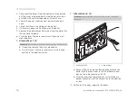
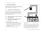
If you fit the radio receiver unit in the boiler, the electrical
connections are made by contact between the controller's
pin header connector and the mating connection on the
boiler. Wiring up the radio receiver unit is only required if
you have mounted it on a wall.
5.2
Connecting the radio receiver unit installed
in the living room
5.2.1
Connecting the radio receiver unit to the
boiler with a "3-4-5 Terminal"
1.
Switch off the boiler.
2. Disconnect the power supply to the boiler.
3. Disconnect the boiler from the power mains by pulling
out the mains plug or de-energising the boiler using a
partition with a contact opening of at least 3 mm.
4. Secure the power supply to the boiler against being
switched back on again.
5. Check that there is no voltage in the boiler.
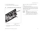
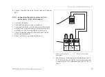
1
2
1
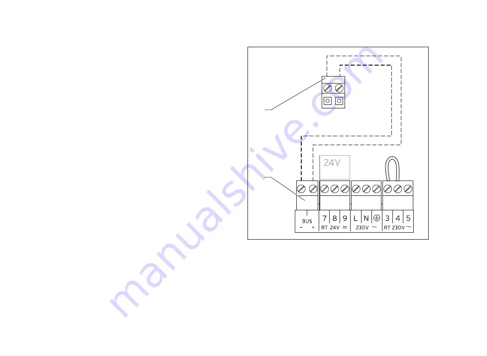
Radio receiver unit ter-
minal block
2 Boiler terminal strip
6. Check whether the bridge is installed between termin-
als 3 and 4 on the PCB of the electronics box and, if re-
quired, install the bridge between terminals 3 and 4.
7. Connect the eBUS line to the terminal block
(1)
in the
wall-mounting base of the radio receiver unit.
Содержание VRT 350f
Страница 1: ...For the competent person Installation instructions VRT 350f VRT 350f GB IE Installation instructions...
Страница 4: ...Contents 4 Installation instructions VRT 350f 0020131978_00 12 Customer service 32...
Страница 33: ......
Страница 34: ......
Страница 35: ......


