


VAM 6 MWN-I_EN - 09/14 - Vaillant
7
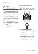
5.4
Valve connections
The units have the following connections and shut off valves:
-
Gas (G) and liquid connections (L): they carry the
refrigerant between the outdoor and indoor unit.
-
Discharge connections for condensate water: they allow
the condensed water to be properly discharged which is
created during the normal operation of the unit.
-
Electric connections: these supply electric energy to the
unit.
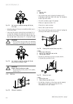
6
Transport
a
DANGER of injury and physical damage!
During transport and unloading, the unit
could fall and injure anyone within the imme
-
diate vicinity
.
To avoid this:
• Only use transport and lifting gear with suita
-
ble load capacity for the unit weight.
• Use only the transport and lifting gear cor
-
rectly (consult the respective user manuals).
• Use the slinging points provided for this pur
-
pose on the unit.
• Secure the unit correctly using propriety
fixings in the mounting points provided.
• Always use suitable personal protection equip
-
ment (helmet, gloves, safety boots and protec
-
tive glasses).
7
Unpacking
a
DANGER of injury and physical damage!
During unpacking you could get injured.
To avoid this:
• Use lifting gear with suitable load capacity for
the unit weight.
• Only use the transport and lifting gear cor
-
rectly (consult the respective user manuals).
• Use the slinging points provided for this pur
-
pose on the unit.
• Always use suitable personal protection equip
-
ment (helmet, gloves, safety boots and protec
-
tive glasses).
Unpack the unit and check that:
-
All parts have been supplied with the system.
-
All the parts and accessories are in perfect condition
.
If parts are damaged or missing please contact your supplier
immediately
.
a
WARNING!
Protect the environment.
• Dispose of the packaging following the local
environmental standards in force. Do not dis
-
pose of packaging irresponsibly, recycle where
possible.
8
Installation
8.1
Qualification of the installation personnel
Ensure that this unit is installed by suitably qualified
personnel. All installers must hold a suitable safe handling of
refrigerants qualification
.
8.2
General precautions to be taken into account
before starting the installation
a
DANGER of injury and physical damage!
During unpacking you could get injured.
To avoid this:
• Only use lifting gear with suitable load capac
-
ity for the unit weight.
• Use the transport and lifting gear correctly
(consult the respective user manuals).
• Use the slinging points provided for this pur
-
pose on the unit.
• Always use suitable personal protection equip
-
ment (helmet, gloves, safety boots and protec
-
tive glasses).
a
DANGER of injury and physical damage!
• The unit should be installed in accordance with
the Regulations and Standards for refrigeration,
electrical and mechanical installation pertain
-
ing to the country in which the installation is
being undertaken.
a
DANGER!
Danger of electric shock. All appliances must
be earthed.
• Connect the earth cable to the correct earthing
point (do not connect to the gas pipe, water
pipe, lightning conductor or telephone line).
a
DANGER!
Danger of electric shock.
• Ensure the appliance is protected by a correctly
rated circuit breaker.
EN
INSTALLATION


