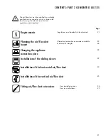
Vaillant ecoMAX pro 28 E Скачать руководство пользователя страница 19

19

PA

R

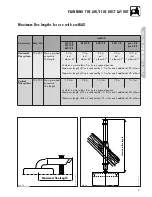
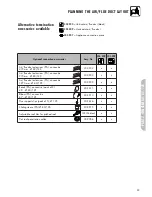
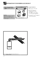
T 1 CONCENTRIC 60/100

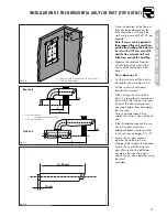
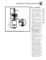
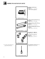
FITTING AIR/FLUE DUCT EXTENSIONS 

Offset

Length of

[in mm]

air conduit

[in mm]

Offset

Length of

[in mm]

air conduit

[in mm]

Offset

Length of

[in mm]

air conduit

[in mm]

690

480

695

485

700

490

705

495

710

500

715

505

720

510

725

515

730

520

735

525

740

530

745

535

750

540

755

545

760

550

765

555

770

560

775

565

780

570

785

575

790

580

795

585

800

590

470

260

475

265

480

270

485

275

490

280

495

285

500

290

505

295

510

300

515

305

520

310

525

315

530

320

535

325

540

330

545

335

550

340

555

345

560

350

565

355

570

360

575

365

580

370

585

375

590

380

595

385

600

390

605

395

610

400

615

405

620

410

625

415

630

420

635

425

640

430

645

435

650

440

655

445

660

450

665

455

670

460

675

465

680

470

685

475

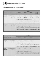
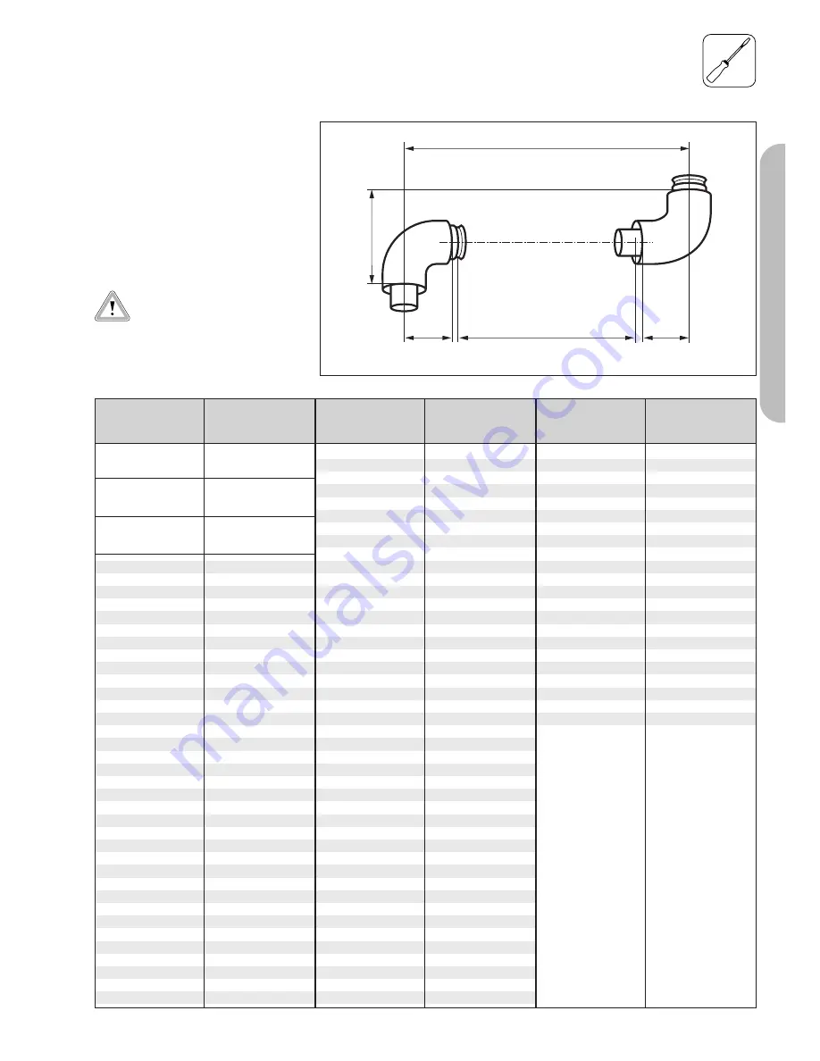
Table 10.1: Length of surplus with 87° elbows

> 190 to

< 210 mm

0

> 215 to

not

< 265 mm

possible

> 270 to

< 290 mm

80

295

85

300

90

305

95

310

100

315

105

320

110

325

115

330

120

335

125

340

130

345

135

350

140

355

145

360

150

365

155

370

160

375

165

380

170

385

175

390

180

395

185

400

190

405

195

410

200

415

205

420

210

425

215

430

220

435

225

440

230

445

235

450

240

455

245

460

250

465

255

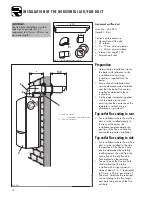
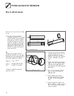
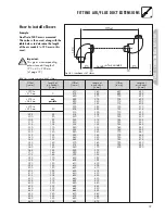
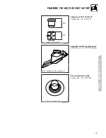
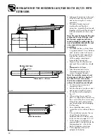
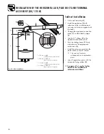
How to install elbows

Example:

An offset of 400 mm is measured.
This value is then used, along with the
table below, to determine the length
of the air conduit ( = 190 mm in this
case).

Important:

This gives a corresponding
exhaust-conduit length of 
190 + 40 = 230 mm. 
(cf. page 19)

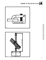
Fig. 10.1:  Installation of 87° elbows

190

Offset

Lenght of air conduit

95

95

10

10

GU_LAZ 102/2GB

Содержание ecoMAX pro 28 E

Страница 1: ...aller Flue installation instructions Air flue duct for use with ecoMAX ecoMAX 613 2 E ecoMAX 618 2 E ecoMAX 622 2 E ecoMAX 824 2 E ecoMAX 828 2E ecoMAX 835 2E ecoMAX pro 18 E ecoMAX pro 28 E GB 200022...

Страница 2: ...2...

Страница 3: ...25 PART 1 Pages 4 20 Standard Concentric Systems 60 100 Aluminium air duct plastic flue duct PART 2 Pages 21 40 Optional Concentric System 80 125 Aluminium air duct plastic flue duct PART 2 CONCENTRIC...

Страница 4: ...ons and standards Requirements Planning the air flue duct layout Regulations and standards to be observed 5 Alternative termination accessories available 6 Maximum flue lengths 9 Installation of the v...

Страница 5: ...erson who is registered with CORGI The Council for Registered Gas Installers The installation of the boiler and flue must be in accordance with the Gas Safety Installation and Use Regulations 1998 and...

Страница 6: ...ntric 970 mm 60 100 Air flue duct extensions concentric 1970 mm 60 100 Bends PP concentric pack of 2 45 60 100 Elbow concentric 87 60 100 Flue support clips pack of 5 100 Sliding sleeve PP 60 100 Adju...

Страница 7: ...2 7 Fig 1 2 Elbow joints 60 100 Elbow 87 60 100 Vaillant Accy No 303 910 Bends 45 pack of 2 60 100 Vaillant Accy No 303 911 Air flue duct extension 470 mm 60 100 Vaillant Accy No 303 902 Air flue duct...

Страница 8: ...4 33 56 Fig 1 5 Offset section 60 100 Offset section 60 100 Vaillant Accy No 303 919 303919_IAx Fig 1 8 Flat roof penetration collar GU_LAZ 42 0 Flat roof penetration collar Vaillant Accy No 009 056 F...

Страница 9: ...87 828 2 E 835 2 E pro 18 E pro 28 E 10 0 m 7 0 m 10 0 m 8 0 m incl 1 elbow 87 4 0 m incl 1 elbow 87 10 0 m incl 1 elbow 87 824 2 E 9 0 m 7 0 m incl 1 elbow 87 613 2 E 618 2 E 622 2 E ecoMAX of which...

Страница 10: ...he air duct clamp 7 over the air duct Pull back the sliding sleeve so that it engages into the socket 3 of the boiler 4 Ensure that the sliding sleeve penetrates the socket such that there is at least...

Страница 11: ...w 1 x 70 mm air duct clamp 1 x 40 mm air duct clamp Internal trim ring 100 External wall seal See page 6 et seq for details of air flue duct elements Fig 3 0 Horizontal air flue conduit Important The...

Страница 12: ...entreline of the template is vertical using a plumbline or spirit level Top outlet flue exiting to rear For installations where the air flue duct is to be installed directly to the rear of the boiler...

Страница 13: ...important to remove any burrs with a file this ensures easy fitting of the ducts and prevents any rough edges from damaging the flue seals Care should be taken not to scratch the white surface of the...

Страница 14: ...iler installation instructions Fit the elbow to the boiler by inserting the spigot of the flue elbow into the flue socket on the boiler and secure using the air duct clamp provided Pull the air flue d...

Страница 15: ...ine the installation site for the boiler with reference to the installation and servicing instructions supplied with the boiler Ensure that all installation and service clearances are available and th...

Страница 16: ...This permits easy separation between the air flue duct and the appliance Drill two holes 3 mm through the air duct of the flue boiler clamp at the most convienient holes on the air duct clamp Ensure t...

Страница 17: ...e boiler See pages 19 et seq for further details on the installation of extensions and elbows Push the sliding sleeve 4 firmly into place on the extensionn Join the vertical roof duct 5 to the extensi...

Страница 18: ...duit Lair length of air conduit Minimum length of air conduit extension 80 mm 1 2 13 2 70 L air Lexhaust 1 2 40 mm 27 1 Fig 9 1 Cutting tubes to size The seals are sensitive to mineral oil based greas...

Страница 19: ...0 635 425 640 430 645 435 650 440 655 445 660 450 665 455 670 460 675 465 680 470 685 475 Table 10 1 Length of surplus with 87 elbows 190 to 210 mm 0 215 to not 265 mm possible 270 to 290 mm 80 295 85...

Страница 20: ...420 mm Important This gives a corresponding exhaust conduit length of 284 40 324 mm cf page 19 GU_LAZ 103 2GB Fig 10 2 Installation of 45 bends 325 320 445 330 327 450 335 334 455 340 341 460 345 348...

Страница 21: ...ments Planning the air flue duct layout Regulations and standards to be observed 22 Alternative termination accessories available 23 Maximum flue lengths 26 Changing the appliance connection piece 28...

Страница 22: ...n instructions are observed The installation of the boiler and its flue must be carried out by a competent person who is registered with CORGI The Council for Registered Gas Installers The installatio...

Страница 23: ...ct extensions PPs concentric 470 mm 80 125 303 202 x Air flue duct extensions PPs concentric 970 mm 80 125 303 203 x Air flue duct extensions PPs concentric 1970 mm 80 125 303 205 x Bends PPs concentr...

Страница 24: ...ow PPs 87 80 125 Vaillant Accy No 303 210 Bends PPs 45 pack of 2 80 125 Vaillant Accy No 303 211 Air flue duct extension PPs 470 mm 80 125 Vaillant Accy No 303 202 Air flue duct extension PPs 970 mm 8...

Страница 25: ...tched roof Adjustable roof tiles for pitched roof Vaillant Accy No 009 076 black GU_LAZ 41 0 164 120 Fig 1 5 Sliding sleeve 80 125 Sliding sleeve PPs 80 125 Vaillant Accy No 303 215 GU_LAZ 76 0 Fig 1...

Страница 26: ...n exposed position Maximum length of flue is reduced by 2 0 m for each additional 90 elbow Maximum length of flue is reduced by 1 0 m for each additional 45 elbow Accessories Accy No Vertical flue sys...

Страница 27: ...27 PART 2 CONCENTRIC 80 125 PLANNING THE AIR FLUE DUCT LAYOUT Maximum flue length Maximum flue length LAS Euro B S 074 0 LAS Euro B S 074 0 Fig 1 9 Fig 1 8...

Страница 28: ...remove it Push the appliance connection piece with the selected connection diameter down from above inserting the push in end onto the sleeve of the flue collecting chamber Now push the appliance conn...

Страница 29: ...Place the air duct clamp 7 over the air duct Pull back the sliding sleeve so that it engages into the socket 3 of the boiler 4 Ensure that the sliding sleeve penetrates the socket such that there is...

Страница 30: ...rizontal air flue duct 87 elbow 2 x 70 mm air duct clamps 2 x internal trim rings 125 See page 24 et seq for details of air flue duct elements Fig 4 1 Horizontal air flue conduit GU_LAZ 82 0 Important...

Страница 31: ...and flue termination are in accordance with these instructions prior to drilling any holes for the boiler hanging bracket Once the position of the flue exit hole has been determined the hole should b...

Страница 32: ...and remove the 3 screws Separate the ducts Note For assembly reasons do not shorten any air duct to a length of less than 100 mm If necessary shorten two adjacent extensions to achieve the overall req...

Страница 33: ...al assembly through the flue exit hole until it protrudes 220 mm out from the outside wall Ensure that the terminal is correctly positioned with the air inlet grille at the bottom Slide one of the two...

Страница 34: ...bow 5 to the appliance connection piece Push the sliding sleeve 7 firmly into place on the appropriate extensionns 6 Install the extensions and join the clutch sleeve to the 87 elbow This section func...

Страница 35: ...Preparation Determine the installation site for the boiler with reference to the installation and servicing instructions supplied with the boiler Ensure that all installation and service clearances a...

Страница 36: ...ly into place on the extensionn Join the vertical roof duct 5 to the extension 7 Join the sliding sleeve 4 to the appliance s connection piece 8 This permits easy separation between the air flue duct...

Страница 37: ...he boiler See pages 41 et seq for further details on the installation of extensions and elbows Push the sliding sleeve 4 firmly into place on the extensionn Join the vertical roof duct 5 to the extens...

Страница 38: ...ue conduit Lair length of air conduit Minimum length of air conduit extension 100 mm 1 2 15 1 2 70 L air Lexhaust 1 2 40 mm 25 Fig 10 1 Cutting tubes to size The seals are sensitive to mineral oil bas...

Страница 39: ...415 630 420 635 425 640 430 645 435 650 440 655 445 660 450 665 455 670 460 675 465 680 470 685 475 690 480 695 485 700 490 705 495 710 500 715 505 720 510 725 515 Table 11 1 Length of surplus with 9...

Страница 40: ...t 284 mm and the height 420 mm Important This gives a corresponding exhaust conduit length of 284 40 324 mm cf page 41 GU_LAZ 103 2GB Fig 11 2 Installation of 45 bends 335 334 455 340 341 460 345 348...

Страница 41: ...41...

Страница 42: ...42...

Страница 43: ...43...

Страница 44: ...44 49 GB 03 08 2002 M Subject to alteration Head Office Service Solutions 0870 6060 777 Vaillant Ltd Vaillant House Technical Advice 01634 292392 Medway City Estate Trident Close Rochester Kent ME2 4...

Отзывы: