


12
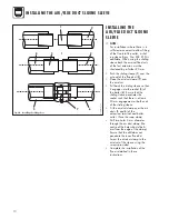
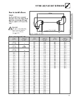
INSTALLATION OF THE HORIZONTAL AIR/FLUE DUCT
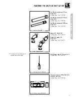
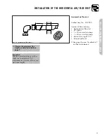
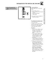
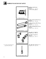
Horizontal air/flue duct
Accy No.: 303 930
(Length 0.8 m)
Contents of the accessory:
• Horizontal air/flue duct
• 87° elbow
• 2 x 70 mm air duct clamps
• 1 x 40 mm air duct clamp
• Internal trim ring Ø 100
• External wall seal.
Fig. 3.1: Horizontal air/flue conduit
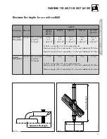
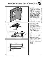
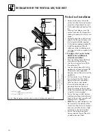
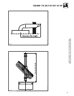
IMPORTANT:
The flue hole should be cut with a
slight rise to outside if 3° ± 1°
(equivalent to 50 mm ± 20 mm rise
per metre length).
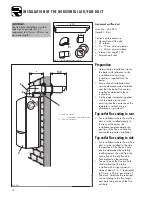
Preparation
• Determine the installation site for
the boiler with reference to the
installation and servicing
instructions supplied with the
boiler.
• Ensure that all installation and
service clearances are available
and that the boiler flue can be
installed as detailed in these
instructions.
• Fix the paper template, supplied
with the boiler, to the wall
ensuring that the centreline of the
template is vertical using a
plumbline or spirit level.
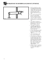
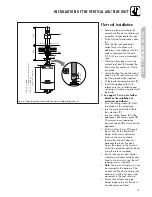
Top outlet flue exiting to rear
• For installations where the air/flue
duct is to be installed directly to
the rear of the boiler, the
installation template details the
position of the flue exit hole for
horizontal top outlet installation.
Top outlet flue exiting to side
• For installations where the air/flue
duct is to be installed to the side,
the position of the flue exit hole
can be determined by carefully
levelling across the wall from the
centre line of the air/flue duct
hole marked on the template.
• The position of the flue exit hole
should allow the flue to be
installed with a slight upward
slope of about 3° ± 1° (equivalent
to 50 mm ± 20 mm per metre of
flue duct). Calculate the required
rise according to the flue length
and mark the position of the flue
exit hole.
800
40
13
70
LAS Euro B/S 037/0
5
190
150
6
6
2
3
Fig. 3.1a
LAS Euro B/S 072/0GB
*
*
= 190 mm ecoMAX
combination and system boilers
*
= 176 mm ecoMAX pro