7 Gas supply adjustments (Commissioning Part II) 7
Instructions for installation and servicing aquaPLUS VUI 362-7
30
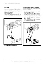
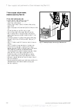
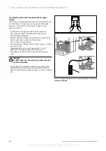
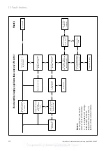
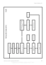
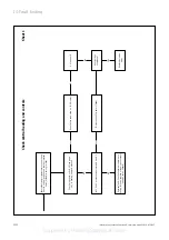
7.6 Checking the gas valve mid setting point
To ensure the most efficient operation of the boiler a
gas valve mid setting point is necessary.
This mid setting point has been factory set and
adjustment of this point is only required after
exchanging either the electronic circuit board or gas
valve or converting the boiler to another gas type.
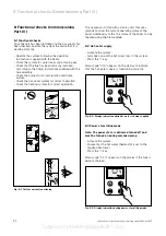
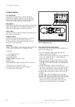
To check the mid setting point proceed as follows.
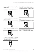
• Turn off the boiler at the main ON/OFF control.
• Press and hold the ”+” button,,while pressing the
button turn the main ON/OFF control to the ”I” ON
position.
• Continue holding ”+” button until display starts to
alternate between the P numbers (P1,P2,P3,P11,P12
and P13).
Release ”+” button.
• Press ”+” button until ”P3 ” (mid setting point) is
shown in display.
• Press ”i” button to operate boiler at mid setting point.
• The burner pressure should now read the mid setting
point pressure for the gas type used,as detailed in
the table below.
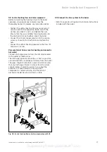
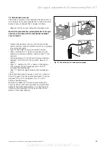
If the mid setting point pressure is incorrect it can be
adjusted as follows.
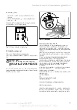
Turn off the boiler at the main ON/OFF control.
• Press and hold the ”+” button,,while pressing the
button turn the main ON/OFF control to the ”I” ON
position.
• Continue holding ”+” button until display starts to
alternate between the P numbers (P1,P2,P3,P11,P12
and P13).
Release ”+” button..
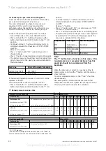
• Press ”+” button until ”P11 ” ((or natural gas)or "P 13"
(for LPG) is shown in display.
• Press ”i” button to operate boiler at mid setting point.
• The mid setting point burner pressure is now adjusted
by pushing the "+"button until the gauge equals the
pressure as detailed in the table below.
Note!
The "-" button has no function in this mode, if the
required pressure is exceeded during set up, this
operation should be recommenced from the
beginning.
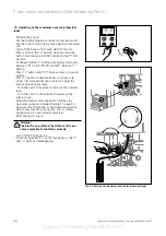
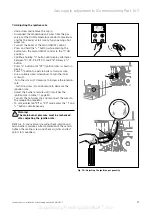
When the pressure is correct, to save the setting to
memory, press and hold the "i"button until the display
stops flashing.
To cancel selected mode press the "i"and "+"buttons
simultaneously.
Re-check ignition and main burner pressures.After
completion of these tests tighten the sealing screw and
check all joints and test points for soundness.
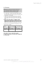
Gas type
Mid setting point pressure
Natural Gas (G20)
5.3 mbar
LPG (G30/31)
15.3 mbar
Program No.
Gas type
Mid setting point
P.11
Natural Gas
5.3 mbar
(G20)
P.12
Not applicable -
for GB
P.13
LPG (G30/31)
15.3 mbar
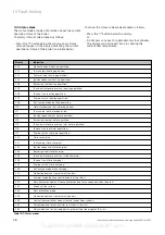
7.7 Burner pressure and gas rate
1)
15 °C, 1013 mbar, dry
2)
The nozzles are stamped with the mark shown in this table. The
marking corresponds to the nozzle hole diameter multiplied by 100.
Gas Rate aquaPLUS
Output [kW]
Delivered Gas
10,5 12,0 16,0 18,0 20,0 24,0 28,0 30,0 33,0 36,9
Natural gas 2H
Gas rate
1)
[m
3
/h] for G20
1.3
1.4
1.9
2.2
2.4
2.8
3.3
3.5
3.9
4.3
Main burner jet mark
2)
7/120
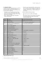
Burner Pressure aquaPLUS
Ignition
Output [kW]
Delivered Gas
rate
10.5 12.0 16.0 18.0 20.0 24.0 28.0 30.0 33.0 36.9
Natural gas 2H
Burner pressure
1)
[mbar] for G20
1.1
1.1
1.4
2.4
2.9
3.65.0
6
.7
7.5
9.0
11.0
Main burner jet mark
2)
7/120
Setting-up program: P11
mid. setting point pressure: 5.3 mbar
L.P.G. 3+
Burner pressure
1)
[mbar] for G30
2.8
2.8
3.5
5.9
7.3
8.9 12.616
.8 19.1 22.9 28.2
Main burner jet mark
2)
7/072
Burner pressure
1)
[mbar] for G31
3.5
3.5
4.4
7.3
9.1
11.1
15.620.8 23.7 28.3 34.9
S
etting-up program: P13
mid. setting point pressure: 15.3 mbar
Supplied by HeatingSpares247.com

