background image

VUI 362-7

Gas fired room sealed fan assisted

combination boiler 

with integrated 15 litre 

power store

For the installer

GB

Instructions for installation and servicing

aquaPLUS

Supplied by HeatingSpares247.com

Содержание aquaPlus

Страница 1: ...362 7 Gas fired room sealed fan assisted combination boiler with integrated 15 litre power store For the installer GB Instructions for installation and servicing aquaPLUS Supplied by HeatingSpares247...

Страница 2: ...ue system to the boiler 17 5 11 Electrical installation 18 5 12 Connection to the main supply 18 5 13 Electronic board layout 20 5 14 Controls 21 5 15 Thermostatic radiator valves 22 Page 5 16 Frost p...

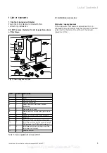
Страница 3: ...door 4 1 Lower cover plate packed in bottom packaging 5 1 Cold water inlet valve 6 3 Flow and return service value gas service valve 7 5 Copper tails for gas and water pipework 8 1 Template 9 2 Guaran...

Страница 4: ...the standard concentric flue system 100 mm outside diameter and a larger diameter concentric flue system 125 mm outside diameter which allows longer flue lengths to be achieved Flue extensions and add...

Страница 5: ...atural gas 20 mbar Gas supply G20 Gross CV s t 37 8 MJ m3 Gas burner pressure max rate 11 0 mbar Gas burner pressure ignition rate 1 1 mbar Gas rate max DHW 4 3 m3 h CH temperature flow range 35 82 C...

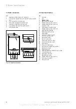
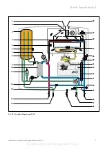
Страница 6: ...n 3 Power store 4 Main heat exchanger 5 Temperature sensor NTC I 6 Temperature sensor NTC III 7 Diverter valve 8 DHW pressure relief valve 9 Temperature sensor NTC IV 10 DHW heat exchanger 11 DHW expa...

Страница 7: ...n 3 Instructions for installation and servicing aquaPLUS VUI 362 7 7 6 3 8 11 12 9 13 25 14 15 16 17 18 19 20 21 22 23 10 7 26 4 5 1 2 24 27 28 29 30 Fig 3 2 Functional Diagram aquaPLUS Supplied by He...

Страница 8: ...ctrical provisions of the Building Regulations Scotland and in IE the current edition of IS 813 and the current ETCI rules in respect of the installation of a boiler in a room containing a bath or sho...

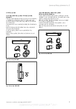
Страница 9: ...rtical flue system is also available Art No 303 800 Refer to flue system installation instructions for full details Fig 4 1 Art No 303 807 Fig 4 2 Art No 303 800 48 1285 603 48 750 48 4 4 5 2 Extended...

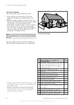
Страница 10: ...ended that a fanned flue terminal should be positioned as follows a at least 2 m from an opening in a building directly opposite and b so that the products of combustion are not directed to discharge...

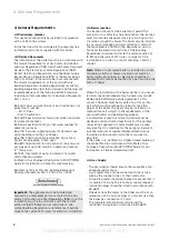
Страница 11: ...ld be at least 1 2 in BSP nominal size and be in accordance with BS 2879 The boiler is suitable for use with minibore or microbore systems Copper tubing to BS 2871 Part 1 should be used for water carr...

Страница 12: ...ves and no additional by pass is required 4 9 10 Venting The boiler is fitted with an automatic air vent Additional provision should be made to enable the heating system to be vented during filling an...

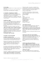
Страница 13: ...Fig 5 1 Dimensions of boiler 440 800 497 Note If the boiler is to be fitted in a timber framed building it should be fitted in accordance with Institute of Gas Engineers Publication IGE UP 7 1998 Gui...

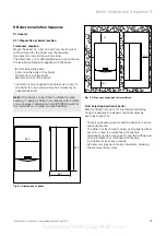
Страница 14: ...le 2 indicates top outlet flue with flue turret facing rearward Mark the position of the hanging bracket fixing holes 1 Drill 2 holes 10 mm for the hanging bracket Top outlet rear exit Mark the centre...

Страница 15: ...the boiler slowly onto the hanging bracket so that the slots at the rear of the boiler fully engage onto the hanging bracket 1 1 3 2 Note If the boiler is to be fitted in a timber framed building ens...

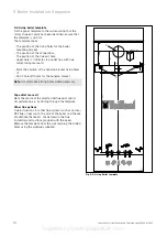
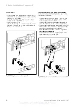
Страница 16: ...nlet and hot water outlet Flush all foreign matter from the mains supply before connecting to the boiler Connect the cold water service valve 1 to the cold inlet water connection 3 of the appliance wi...

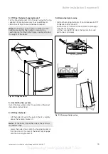
Страница 17: ...t the central heating pipework to the flow 9 and return 4 tails Pressure Relief Valves central heating and domestic hot water Connect discharge pipes not less than 15 mm diameter to the outlet of thes...

Страница 18: ...3 x 0 75 to 3 x 1 5 mm2 should be used Warning This appliance must be earthed Important Ensure that all cords pass through the cable clamps in the rear of the control box and are securely fixed Ensure...

Страница 19: ...equence 5 Instructions for installation and servicing aquaPLUS VUI 362 7 19 Fig 5 9 Exposed rear view of switchgear cabinet Fig 5 10 Wiring system 3 N L 9 8 7 5 4 3 RT 24V 230V RT 230V 1 2 Supplied by...

Страница 20: ...ve Socket X7 for accessory box connection Socket X8 for VRC VC connection Room thermostat 230 V connections 3 4 and 5 Mains power supply connections L N and earth Socket X12 pump connection Socket X14...

Страница 21: ...N 4 L N 3 3 4 1 2 3 4 3 L N 2 3 4 L N 3 4 1 3 4 3 4 5 5 Connection details for external time switches and boiler terminal strip Fig 5 13 shows the connection details where a time switch is used witho...

Страница 22: ...y are used in conjunction with a programmable room thermostat or separate timer and room thermostat to ensure complete boiler shut down when the heating demand is satisfied The radiator in the room co...

Страница 23: ...ventilation extinguish all naked flames and do not smoke whilst purging After purging the gas service valve connection must be retightened and tested for soundness The boiler itself does not require p...

Страница 24: ...holding button until display alternates between P1 P2 P3 P11 P12 and P13 Release button Press button until P1 full gas rate is shown in display Press i button to operate boiler at full gas rate Check...

Страница 25: ...ld the button while pressing the button turn the main ON OFF control to the 1 ON position Continue holding button until display alternates between P1 P2 P3 P11 P12 and P13 Release button Press button...

Страница 26: ...13 Release button Press button until P1 full gas rate is shown in display Press i button to operate boiler at full gas rate Using a 10 mm spanner turn nut 2 to adjust the burner operating pressure Tur...

Страница 27: ...own in display Press i button to operate boiler at full gas rate Use a suitably sized screwdriver to turn the inner screw 2 Turn the screw 2 clockwise to increase the ignation rate Turn the screw 2 an...

Страница 28: ...fy required range rating setting and note main burner pressure in mbar for that output Turn on the central heating Ensure that any thermostatic radiator valves are open and set to high Simultaneously...

Страница 29: ...se the value Observe the U gauge as the button is pushed and stop pushing when the required main burner pressure has been achieved 5 After setting press and hold the i button for five seconds or until...

Страница 30: ...y pushing the button until the gauge equals the pressure as detailed in the table below Note The button has no function in this mode if the required pressure is exceeded during set up this operation s...

Страница 31: ...er side at the top of the boiler engage Push the casing onto the securing clips at the bottom of the boiler Close control panel 2 Secure control panel by turning both securing fasteners 3 clockwise by...

Страница 32: ...on Fig 8 1 Test for correct functioning I 0 This appliance is fitted with a display unit that uses symbols to show the current operating status of the boiler Additionally to this the status of the boi...

Страница 33: ...o reach operating temperature Check that the heating system is watertight Turn the boiler off and rapidly drain both boiler and system while still hot Refill the system and release all air Release wat...

Страница 34: ...ng the surface of the burner Inspect for signs of excessive flame lift or sooting 8 Functional checks Commissioning Part III Servicing 9 Instructions for installation and servicing aquaPLUS VUI 362 7...

Страница 35: ...n vessel charge point Check that the internal charge pressure of expansion vessel is between 0 7 0 9 bar If pressure is lower than this the vessel should be re pressurised using an air pump Refit valv...

Страница 36: ...ation normal flame or lock out crossed out flame Instructions for installation and servicing aquaPLUS VUI 362 7 36 Fig 10 1 Display indications 10 2 Logical fault finding procedure These checks must b...

Страница 37: ...n the boiler display follow the fault finding charts referring also to the status mode table 3 Note If the boiler display is completely blank initially check the two fuses Isolate the electrical suppl...

Страница 38: ...n store charging S 27 Pump over run store charging S 28 Anti cycling mode store charging S 30 No heating demand from external controls S 31 Summer mode heating control knob in off position S 32 Main h...

Страница 39: ...0 Part load setting 0 30 d 01 Water pump over run 1 2 3 60 min factory adjusted to 5 min d 02 Maximum burner anti cycling period at 20 C 8 60 min factory adjusted to 15 min flow temperature d 03 Actua...

Страница 40: ...s d 71 Maximum target value for heating system flow 0 82 C 1 87 C factory adjustment 82 C temperature d 72 Pump over run time after filling hot water store 0 1 2 250 s factory adjustment 80 s d 76 Gas...

Страница 41: ...re protection No water in appliance pump cable defective pump blocked or defective pump output too low F 23 Dry fire protection difference between flow and No water in appliance pump cable defective p...

Страница 42: ...een 5V and GND test points on electronic board Replace LCD display Yes No Repair external fault Is the continuity across fuse F1 Go to sheet B Does ON OFF knob operate switch on electronic board Boile...

Страница 43: ...CD panel Check transformer 230 VAC primary black red and approx 17 VDC secondary blue brown Check replace pump Replace fuse F1 If fan commences operation exchange gas valve After approx 20 secs Does f...

Страница 44: ...g for heat Check diagnostic code D 08 see page 39 Is heating demand present No Is 230 VAC present across terminals 4 and 5 No External fault Check all external controls are calling for heat replace or...

Страница 45: ...onnector for fan speed control Does the fan run now Is 230 VAC present across fan terminals Replace electronic board Yes No No Yes No Yes Yes Check replace fan Does the boiler commence ignition Check...

Страница 46: ...e gas valve as necessary Does burner light No Replace electronic board Yes Is burner indicator illuminated No Check flame rectification lead and electrode Is burner indicator illuminated No Yes Does b...

Страница 47: ...ervice valves are open No No No Replace electronic board No Check operation of boiler in DHW mode does flame increase in size to full rate Yes Check partial load setting No Check diagnostic code D 22...

Страница 48: ...stment is at maximum flow rate Does green warmstart indicator flash now Check Clear impeller in Aquasensor replace if necessary Check replace hall sensor Replace electronic board Does hot water indica...

Страница 49: ...demand indicator Ignition indicator MAIN SWITCHBOARD IGNITION ELECTRODES Legend b blue br brown y g yellow green r red p pink or orange t transparent bl black gr grey w white gr b br y g b br y g br...

Страница 50: ...C coding resistor flow NTC return lifting magnet 24 23 1 12 13 14 15 16 17 18 19 20 21 22 2 3 4 5 6 7 8 9 10 11 fan unit ignition electrodes gas valve diverter valve air pressure switch NTC tank ionis...

Страница 51: ...Fig 10 6 Warmstart NTC Main heat exchanger 065 087 Fig 10 7 Expansion vessel 10 l 181 079 Fig 10 8 heating Switch and control board 130 821 Fig 10 9 Main transformer 287 450 Fig 10 10 Pump 160 928 Fi...

Страница 52: ...list 52 Instructions for installation and servicing aquaPLUS VUI 362 7 Fig 10 1 Fig 10 2 Fig 10 3 Fig 10 5 Fig 10 6 Fig 10 7 Fig 10 8 Fig 10 9 Fig 10 10 Fig 10 11 Fig 10 12 Fig 10 13 Supplied by Heati...

Страница 53: ...icing aquaPLUS VUI 362 7 Fig 10 14 Fig 10 15 Fig 10 16 Fig 10 17 Fig 10 18 Fig 10 19 Fig 10 20 Fig 10 22 For these components please observe the associated installation and removal instructions relati...

Страница 54: ...Instructions for installation and servicing aquaPLUS VUI 362 7 54 Supplied by HeatingSpares247 com...

Страница 55: ...Instructions for installation and servicing aquaPLUS VUI 362 7 55 Supplied by HeatingSpares247 com...

Страница 56: ...003 M Subject to alteration Head Office Vaillant Ltd Service Solutions 0870 6060 777 Vaillant House Trident Close Medway City Estate Rochester Kent ME2 4EZ Technical Advice 01634 292392 Supplied by He...

Страница 57: ...he user GB Instructions for use aquaPLUS Gas fired room sealed fan assisted combination boiler with integrated 15 litre power store 83 46 41_10_GB_04 2003 11 04 2003 9 11 Uhr Seite 1 Supplied by Heati...

Страница 58: ...stic hot water operation 6 3 3 1 Power store operation 7 3 3 2 Obtaining hot water 7 3 4 Heating operation 8 3 4 1 Setting the maximum radiator temperature control 8 3 4 2 Setting the external control...

Страница 59: ...n check your installer by calling CORGI direct on 01256 372300 1 4 EC designation The purpose of EC designation is to certify that the boiler complies with the requirements of the directives covering...

Страница 60: ...llation and Use Regulations 1998 In the U K CORGI Registered installers undertake the work to a safe and satisfactory standard If the boiler is installed in a compartment do not obstruct any purpose p...

Страница 61: ...e 8 Correct burner operation normal flame or lock out crossed out flame Fig 3 2 Display indications 0 I C o C o VRC VC 1 2 3 7 6 5 4 8 3 Operation 3 1 Overview 3 1 1 Operating controls For access to t...

Страница 62: ...k position to prevent excessive scale formation fig 3 5 VRC VC C o 0 I C o 1 3 2 Initial checks before turning ON 3 2 1 Open the service valves Ensure the cold water service valve is open This can be...

Страница 63: ...erature control knob to the desired setting Note Irrespective of whether the power store facility is switched on or off the boiler will automatically operate to provide hot water whenever a hot water...

Страница 64: ...t period to fully disperse the heat from the boiler Note The boiler incorporates an anti cycling economiser control to prevent energy wasteful ON and OFF operation of the boiler for short periods when...

Страница 65: ...the flame can then only be performed after pressing the Reset button Press the Reset button 2 fig 3 11 and hold for approx 1 second Warning If the boiler still shuts off after a third attempt then pl...

Страница 66: ...2 Reset 3 6 1 Faults in the hot water system To protect the power store feed pump the appliance is equipped with dry running protection This prevents operation of the feed pump if an insufficient quan...

Страница 67: ...is not operated for several hours during very cold weather there is therefore the possibility of the system freezing Please ensure that if you are absent during a period of frost the central heating r...

Страница 68: ...n Head Office Vaillant Ltd Service Solutions 0870 6060 777 Vaillant House Trident Close Medway City Estate Rochester Kent ME2 4EZ Technical Advice 01634 292392 83 46 41_10_GB_04 2003 11 04 2003 9 11 U...

Отзывы: