


27
MKHF | MKHS
Montageanleitung
Mounting instructions
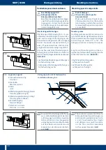
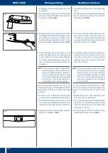
Reparatur eines defekten Heizkabels
Beschädigte oder defekte Heizkabel kön-
nen nicht repariert werden und müssen
deshalb komplett ausgetauscht werden
Zum Austausch von Heizkabeln wie folgt
vorgehen:
▸ Komplettes Entfernen des Heizkabels
entsprechend Seite 26
▸ Die Wiedermontage des Heizkabels
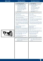
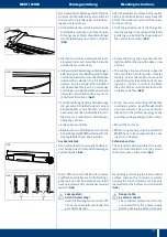
Verlegung im Anschlusskasten
Die linke und rechte Einspeisung ist geeig-
net für Anlagen mit einem Heizabschnitt
oder als Endeinspeisung bei mehreren
Heizkreisen
Die Mitteneinspeisung ist für zwei oder
mehrere Heizabschnitte vorgesehen
Zur Installation der Heizkabel wie folgt
vorgehen:
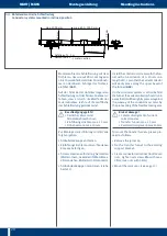
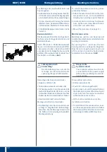
S
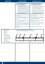
Kabelausdehnung
berücksichtigen!
Die Schlaufenlänge des Heizkabels
muss bei 15–20 °C mittig im Freiraum
des Anschlusskastens liegen, damit
sich das Heizkabel bei Erwärmung
ausdehnen kann
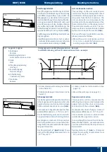
▸ Heizkabel (
1
) (
G49/G50
) unter Beachtung
der Schlaufenlängen auf Länge schnei-
den
▸ Drahtgeflecht des Heizkabels auf etwa
40 mm Länge absetzen
▸ Isolierung des Heizdrahtes auf etwa
12 mm entfernen und umbiegen
Repairing a defective heating cable
Damaged or defective heating cables can-
not be repaired and therefore have to be
completely replaced
To replace heating cables, proceed as fol-
lows:
▸ Completely remove the heating cable
according to page 26
▸ Reinstall the heating cable
Installation in the terminal box
The left and right feed is appropriate for
installations with one heating section or
as an end feed if there are several heating
circuits
The middle power feed is intended for two
or more heating sections
Proceed as follows to install the heating
cables:
S
Take the cable expansion
into consideration!
At 15–20 °C, the loop length of the
heating cable has to be positioned
centrally in the clear space of the
terminal box, so that the cable can
expand in case it is heated
▸ Cut the heating cable to length (
1
) (
G49/
G50
), taking the loop lengths into ac-
count
▸ Remove the wire mesh of the heating
cable by a length of about 40 mm
▸ Take off the insulation of the heating wire
by about 12 mm and bend it
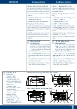
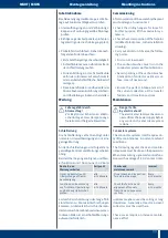
G49
G50
5
7
1
2
3
4
8
1
3
2
8
G49 Linke Endeinspeisung | Left-hand end power feed
Legende | Legend
1
Heizkabel
Heating Cable
2
Serienverbinder
Connection terminal
3
Anschlussleitung 1,5 mm
2
Connection cable 15 mm
2
4
Klemmstein
Clamping device
5
Kundenseitiger Anschluss
max 2 x 4 mm
2
Cable connection from customer
max 2 x 4 mm
2
6
Gehäuseöffnung
Housing opening
7
Kabelverschraubung
Cable gland
8
Zugentlastung Heizdraht
Strain relief heating cable
G50 Mitteneinspeisung | Middle power feed
5
7
2
3
5
7
3
2
4
8
3
1
1
6