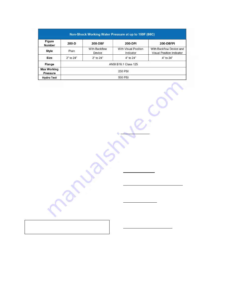
3
open top sealed with a cast cover (2). The
flexible disc (3) is retained by the cover.
An optional valve mounted position indicator,
with or without limit switch, is available to
provide local and remote position indication.
These also can be field installed (see Page 4).
An optional backflow actuator is available to
manually open the valve to allow reverse flow.
The backflow device can be easily installed in
the field (see Page 5).
INSTALLATION
The Figure 200 Rubber Flapper Check
Valve must be properly installed for proper
operation. It may be installed in either horizontal
or vertical (flow-up) applications. However,
when horizontal, the valve must be installed with
the nameplate facing up. In all installations, the
arrow cast in the valve cover must be pointed in
the direction of forward flow.
Do not remove flange protectors until ready to
install and ensure there is no debris inside the
valve before installation.
Flanged valves should only be mated with flat-
faced pipe flanges equipped with full-face
gaskets.
CAUTION
The use of ring gaskets or mating flanges with a
raised face may damage valve flanges.
The valve and adjacent piping must be
supported and aligned to prevent imposing
stress on the valve. Once the flange bolts or
studs are lubricated and inserted around the
flange, uniformly hand tighten. Then tighten the
bolts to the recommended torque in graduated
steps using the cross-over tightening method. If
leakage occurs, allow gaskets to absorb fluid
and check torque and leakage after 24 hours.
Do not exceed bolt rating or extrude gasket.
PREVENTIVE MAINTENANCE
The Figure 200 Rubber Flapper Check Valve
requires
no
scheduled
lubrication
or
maintenance. The valve can be inspected or
serviced without removal from the line.
Valve Inspection: If internal inspection of the
valve is required, follow the disassembly
instructions provided below.
TROUBLESHOOTING
Common problems and solutions are presented
below to assist you in troubleshooting the valve
assembly in an efficient manner.
•
Leakage at flanges
Tighten bolts, replace gasket.
•
Valve leaks backwards when closed
Inspect disc for damage and replace. Inspect
metal seating surface; clean if necessary.
•
Valve does not open
Check for obstruction in valve; see Disassembly
procedure below. Operating pressure may
be insufficient to open valve. If less than 0.5
PSIG review application with factory
•
Leakage at Backflow Actuator
Remove line pressure and exercise actuator. If
leak persists, replace seals in actuator; see the
Backflow Actuator Seal Replacement Procedure
on Page 6.
DISASSEMBLY
The valve can be disassembled for inspection or
repair while in the line or when removed if more
convenient. All work on the valve should be
Содержание GA Industries FIGURE 200
Страница 7: ...7 This page intentionally left blank...


