


2
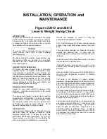
VALVE CONSTRUCTION
The standard Series 220 Swing Check Valve has a
cast iron body, bronze or stainless steel (indicated by
Figure Number suffixed with “S”)
body seat, stainless
steel hinge shaft and cast iron disc with a rubber disc
seat.
An “M” su
ffixed to the Figure Number (e.g.,
220-DM or 220-USM) indicates valve was supplied
with optional metal-to-metal seating was supplied.
Refer to the List of Materials submitted for the order if
non-standard materials were provided.
Refer to Page 4 for details of construction and parts
location.
START-UP
The valve generally does not require any calibration
or adjustment prior to start-up. The counterweight(s)
should be initially placed at the far end of the arm and
secured by tightening the set screw (31A).
The valve should smoothly swing open as flow
through the valve increases. The amount of opening
depends on the flow velocity through the valve and
can be observed by watching the external
counterweight arm
. The valve is “full ported” at
about
25 degrees of swing but can swing open as much as
60 degrees.
Shut down the pump and o
bserve the valve’s closure.
If the valve was less than 60 degrees open and the
closure was smooth and quiet, then the weight(s) may
be moved incrementally toward the shaft. Repeat
these steps to the point where the valve opens to the
extent possible but still closes quietly.
Non-slam
operation
is
achieved
when
the
counterweight closes the valve prior to flow reversal.
In extreme cases, it may be necessary to install
additional counterweight(s) to effect non-slam closure.
PREVENTIVE MAINTENANCE
Figure 220 Swing Check Valves require no scheduled
lubrication, adjustment or preventive maintenance.
A monthly inspection should be performed for the first
6 months of operation to ensure the valve is
functioning properly and there is no external fluid
leakage or audible evidence of water leaking
backwards through the closed valve.
Thereafter, a quarterly visual inspection should be
performed.
TROUBLESHOOTING
•
Shaft packing leakage
Tighten packing gland nuts equally just
enough to stop leakage, no more than ½ turn
at a time. DO NOT OVER-TIGHTEN!
Replace packing if necessary.
•
Leakage past seat when closed
Inspect valve for debris, clean
Inspect seating surfaces for damage, replace
as necessary
•
Leakage past cover or flange gaskets
Tighten cover or flange bolts
•
Disc oscillating when open
Move counterweight(s) toward shaft
•
Valve slams upon closing
Move counterweight(s) toward end of arm
Ensure shaft packing is not too tight
Install additional counterweight(s)
WARNING
Removing the valve from the line or disassembling
the valve while there is pressure in the valve body
may result in injury or damage to the valve
WARNING
Follow all applicable safety regulations and codes and
read and understand all instructions before
undertaking disassembly.
DISASSEMBLY
All Figure 220 valves can be serviced while the body
remains connected to the pipeline. A skilled
technician should perform all work. No special tools
are required.
First ensure there is no pressure within the valve and
operating equipment is tagged and locked out. Refer
to pages 3 and 4 for parts identification and location.
It is not necessary to disassemble the entire valve to
replace the shaft packing, follow steps 1 to 3 and 5a.
1. Ensure there is no pressure within the valve
and operating equipment is locked out.
2. Mark the position of the counterweight(s) on
the arm. Loosen the counterweight set
screw (31A) and slide the weight(s) off the
arm. Loosen the counterweight arm set
screws (30A) and slide the arm (30) off the
shaft, being careful not to lose the key (30B).
3. Loosen and remove the gland stud nuts (16),
slide off the gland (15) and remove the shaft
packing (17).
4. Remove the end plate bolts (35), the end
plate (34) being careful not to lose or
damage the end plate seal (36) unless it is to
be replaced
5. Remove the cover bolts (10) and lift off the
cover (9). If necessary, carefully pry the
cover off using a cold chisel between the
body and cover. Be careful not to damage
or lose the cover gasket (8) unless it is to be
replaced.
6. Remove the shaft lock pin (18) by threading
a screw into the tapped hole.
7. With the disc and disc arm properly
supported, loosen the disc arm set screw
(12) and pull the shaft (11) out of the valve.
It may be necessary to drive out the shaft
from the opposite end.
NOTE: The outer bushing (14) and disc arm
key (19) should come out with the


