VADDIO WALLVIEW PRO EAGLEEYE Скачать руководство пользователя страница 5


WallVIEW Universal PRO EagleEye Installation and User Guide 341-660 Rev. B                                                                  Page 5 of 12 

Step 6: 

Attach the Cat. 5 cables for Power, Video and Control to the Quick-Connect PRO rack mount interface. 
Connect the HD video outputs to the Polycom HDCI break out cable provided either provided with your 
codec, or available from Polycom.  Connect the DB-9 to RJ-45 adapter to the Polycom break out cable, then 
connect the RS-232 control Cat. 5 cable to the RJ-45 port on the adapter (see Appendix 1 for additional 
wiring detail).  Connect the PowerRite 36 VDC power supply to the Quick-Connect PRO power input.     

Note:  Plugging the POWER Cat. 5 Cable into the wrong RJ-45 may cause damage to the camera system and void the warranty. 


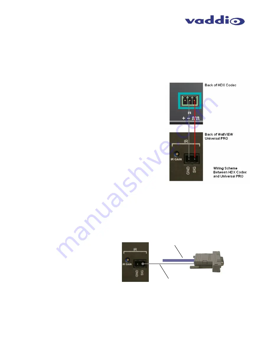
Step 7:  For HDX 9000 Series Installs Requiring IR Pass-Thru 

Connect a two-conductor wire to the connectors of both the 
Polycom HDX codec and Quick-Connect PRO Universal rack 
mount box.  Ground from the Quick-Connect PRO Universal 
should be terminated to the “-“ connector on the HDX 9000 Series 
codec’s IR input.  The Signal “SIG” port on the Quick-Connect 
PRO Universal should be terminated to the square wave symbol.  
See adjacent drawing for additional detail 


Connect the IR output from the Quick-Connect PRO Universal to 
either the IR spring cage IR input on an HDX series codec (where 
available) or a Xantech™ IR probe (compatible models: 282MRP 
or 283M).  The white striped wire on the IR Probe is the Signal 
and the black wire is Ground.   


Step 7:  For EagleEye IR Pass-Thru on HDX 7000 and 8000 Series Codecs 

Using the RJ-45 to DB-9 adapter (998-1004-232) supplied with the system, strip and terminate the single wire 
coming out of the back of the adapter, and connect it to the Phoenix-type connector supplied with the Quick-
Connect PRO.  The wire needs to be terminated to the “SIG” pin on the back of the Quick-Connect PRO.   


Figure 6:

  Wiring Configuration for 

IR Forwarding feature


(optional)


Figure 7:

  Required wiring configuration 

for IR Forwarding from the camera IR 
port to codec.  Note:  There is no IR port 
on the front of the HDX 7000 and 8000 
series codecs.  The IR receiver on these 
codecs is imbedded in the camera.  


RS-232 Cat. 5 

Single wire from the back of 
the RJ-45 to DB-9 adapter, 
connected to the IR Signal 
“SIG” port via a Phoenix-type 
connector 

Содержание WALLVIEW PRO EAGLEEYE

Страница 1: ...Interface Module EZIM and custom break out cable to interface between the EZIM and EagleEye camera Like all Vaddio WallVIEW systems the Thin Profile Wall Mount and mounting hardware is included INTENDED USE Before installing the Vaddio WallVIEW PRO EagleEye Camera System please read the entire manual thoroughly All Vaddio camera systems are designed for use indoors Outdoor operation is not recomme...

Страница 2: ... 568B or A The use of RJ 45 EZ connectors is not recommended Before Installing Locate the camera mounting location paying close attention to camera viewing angles lighting conditions possible line of site obstructions and checking for in wall obstructions Pick a mounting location to optimize the performance of the camera Pre wire all cabling as required from the camera location to the head end equ...

Страница 3: ... IR is fed out of the Quick Connect unit through the RJ 45 to DB 9 adapter to the HDX 7000 8000 series codec for IR forwarding from the camera The Power Video and Control Cat 5 cables can be run up to 500 from the Quick Connect box to the EZ Interface Module which connects to the camera See Step 7 for additional information on HDX 7000 8000 IR wiring NOTE The single wire coming out of the back of ...

Страница 4: ...pped screw holes on the bottom of the EagleEye camera to the four holes of the mount Using the supplied hex head screws feed the screws through the four holes to attach the camera to the mount Step 4 Prior to connecting the Cat 5 cables check cables for proper continuity with a Cat 5 cable tester Attach the Cat 5 cables for Power Video and Control to the EZIM and feed the excess cabling into the w...

Страница 5: ...e Signal SIG port on the Quick Connect PRO Universal should be terminated to the square wave symbol See adjacent drawing for additional detail Connect the IR output from the Quick Connect PRO Universal to either the IR spring cage IR input on an HDX series codec where available or a Xantech IR probe compatible models 282MRP or 283M The white striped wire on the IR Probe is the Signal and the black...

Страница 6: ...ain adjustment is factory set for distances below 300 feet 91 4 meters and should not have to be adjusted unless the Cat 5 cabling distance is over this length For cable runs above 300 feet slowly adjust the gain level up while pressing functions on the remote control pointed at the EagleEye camera using the WallVIEW PRO system Once all remote control functions are operating from the remote throug...

Страница 7: ...IP switch loads camera profiles and IR Forwarding for Polycom HDX 9000 Codecs Video Adjustments Y Gain luminance gain for fine tuning over longer cable distances Distance Compensation 100 200 300 400 IR Gain Adjustment IR Gain for fine tuning IR over 300 feet Compatible Cameras Sony BRC H700 BRC Z700 EVI HD1 BRC 300 EVI D70 EVI D100 also in SD Mode Polycom EagleEye Max Cat 5 Cable Distance Up to 5...

Страница 8: ... control source RS 232 OUT Connector Pin Signal 1 DSR Sony Daisy chain from DTR 2 DTR Sony Daisy chain to DSR 3 Unused 4 Unused 5 Unused 6 Digital GND 7 TXD to RXD of control source 8 RXD from TXD of control source Video Connector Pin Signal SD HD 1 IR IR 2 IR GND IR GND 3 Y Y 4 C PB 5 C PB 6 Y Y 7 Comp Video PR 8 Comp Video PR DB 25 Connector Pins Signal 1 GND Out 14 RXD Out 2 TXD Out 15 DTR Out ...

Страница 9: ... Polycom S1 Connector Pin 3 300 200 POWER 36V 2A 100 400 Y GAIN CAM SELECT Y C Y PB COMP SD PR HD DISTANCE GND SIG CAMERA IR VIDEO ADJUST VIDEO OUTPUTS VIDEO IR GAIN Power Connector Pin Signal 1 Power 2 Power 3 Power 4 Power 5 Power 6 Power 7 Power 8 Power Video Connector Pin Signal SD HD 1 IR IR 2 IR GND IR GND 3 Y Y 4 C PB 5 C PB 6 Y Y 7 Comp Video PR 8 Comp Video PR Polycom HDCI Break out Cable...

Страница 10: ...uthority to operate this equipment ICES 003 Compliance This digital apparatus does not exceed the Class A limits for radio noise emissions from digital apparatus set out in the Radio Interference Regulations of the Canadian Department of Communications Le présent appareil numérique n emet pas de bruits radioélectriques dépassant les limites applicables aux appareils numeriques de la classe A présc...

Страница 11: ...support at support vaddio com or online at www vaddio com Return Material Authorization RMA number Before returning a product for repair or replacement request an RMA from Vaddio s technical support Provide a technician with a return phone number e mail address shipping address and product serial numbers and describe the reason for repairs or returns as well as the date of purchase and proof of pu...

Страница 12: ...71 4400 FAX 763 971 4464 www vaddio com 2008 Vaddio All Rights Reserved Reproduction in whole or in part without written permission is prohibited Specifications and pricing subject to change Vaddio WallVIEW Quick Connect EZIM HSDS and PowerRite are registered trademarks of Vaddio All other trademarks are property of their respective owners Document Number 341 660 Rev B ...

Отзывы: