VADDIO WALLVIEW CCU HE100 Скачать руководство пользователя страница 2

WallVIEW CCU HE100 

Quick-Connect CCU HE100 Installation and User Guide 341-789 Rev. B                                                                            Page 2 of 12 

UNPACKING 

Carefully remove and identify the following parts for the WallVIEW CCU HE100 system: 

  One (1) Panasonic AW-HE100 – Modified 12 VDC Version - with IR Remote 

  One (1) Quick-Connect CCU (998-1105-014) with 2-position Phoenix Type Connector 

  One (1) CCU EZ Interface Module CCU (998-6700-002) EZIM CCU 

  One (1) CCU HE100 25-pin Breakout Cable (440-6707-110) 

  One (1) DB-9F to RJ-45F, RS-232 to RS-422 Adapter (998-1005-232) 

  One (1) CommFront CVT-485_422-1 Port Powered RS-232 to RS-422 Converter  

  One (1) 1’ Cat 5 Patch Cable 

  One (1) Wall Mount AW-HE100 (535-2000-229) and Mounting Hardware 

  One (1) 36V PowerRite Power Supply with AC Cord Set  

  One (1) User Manual (341-789)  

 Documentation 

 Vaddio 

Manual 

 Panasonic 

Manual 


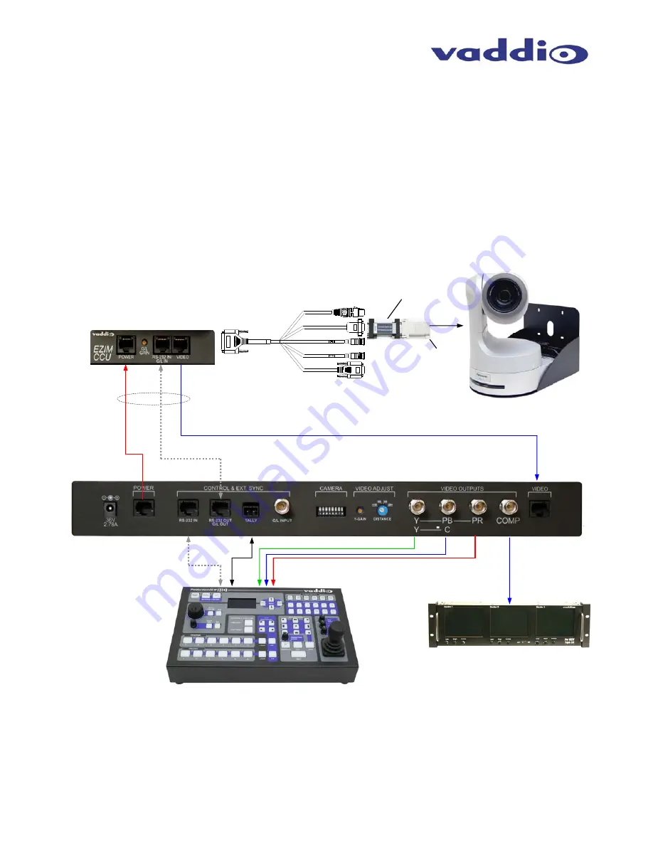
Wiring Diagram Example: 


Figure 2:  

The Quick-Connect CCU System uses a Cat. 5 (all 4-pairs) for power to ensure the motors receive the 

required current to operate properly.  The Video Cat. 5 cable uses all four pairs for video.  The RS-232 Cat. 5 provides 
communication to the camera for CCU and PTZ control and G/L (where applicable) to the camera.  These Cat. 5 
cables can be run up to 500’ (152.4m).  See Appendix 1 for wiring and pin-out information.   NOTE:  A direct RS-232 
Cat. 5 cable is required for each Quick-Connect CCU and camera, with the RS-232 converted to RS-422 at the break 
out cable.  Daisy-Chain is not supported with the AW-HE100 camera.

CAT-5 Cables 

up to 500’ 

HD Break-out 

Cable  

EZIM CCU 

Power 

RS-232 & Gen Lock 

HD & SD (composite) Video on CAT-5  

RS-232 Tally 

ProductionVIEW™ HD 

SD Composite Video to 

PreVIEW™ Monitors 

POWER 
DB-9M to RS-232 to 422 Converter, Cat 5 Adapter 
SD VIDEO OUT  
G/L  
HD VIDEO OUT (Y, Pb, Pr) 

Quick-Connect CCU  

AW-HE100 Camera, Wall Mount 
with EZIM CCU (behind camera) 

Component HD 

Composite 

Video 

+   

G


RS-232 

RS-422 

RS- 232 to 

RS-422 

Converter 

DB-9 F to 

Cat 5 

Содержание WALLVIEW CCU HE100

Страница 1: ...es including Tally illumination on the camera which allows the presenter to know which camera is live as well as Genlock delivered to the camera over CAT 5 INTENDED USE Before installing the Vaddio WallVIEW CCU Camera System please read the entire manual thoroughly All Vaddio camera systems are designed for use indoors Outdoor operation is not recommended has not been tested and could damage the c...

Страница 2: ...uick Connect CCU System uses a Cat 5 all 4 pairs for power to ensure the motors receive the required current to operate properly The Video Cat 5 cable uses all four pairs for video The RS 232 Cat 5 provides communication to the camera for CCU and PTZ control and G L where applicable to the camera These Cat 5 cables can be run up to 500 152 4m See Appendix 1 for wiring and pin out information NOTE ...

Страница 3: ...nto microprocessor memory When lit backlit blue SPDT switch the scene is activated To store a scene the user adjusts the controls and touches and holds the scene button down until the button blinks Detail The Detail control sharpens or softens objects in the frame Red Blue Gain Controls The Red and Blue Gain encoders adjust the red and blue gain of the signal when AWB is disengaged AWB The Automat...

Страница 4: ...a differential amplifier to a receiver at the EZIM CCU The G L gain adjustment is on the EZIM CCU or the receive side of the signal Camera Feature Switches The QCCU interface has an 8 position dip switch on the rear panel to allow future functionality Switch 2 needs to be in the UP position for the AW HE100 to function properly Y Gain Adjusts Y Gain and allows the user to fine tune the video signa...

Страница 5: ...sing four dry wall anchors MOUNTING INSTRUCTIONS Step 1 After determining the optimum location of the camera system mark locations for the four screw holes and cable pass thru vertical oval Install the drywall mounts and cut the hole for the cable pass thru At this point do not install the Wall Mount Step 2 Connect the 25 pin cable to the EZIM CCU Next mount the EZIM CCU and break out cable in the...

Страница 6: ... of control and operation of the cameras the RS 232 controller control system or joystick should be powered on after the camera Setting Up the AW HE Video Format and Output Settings The CCU system is capable of accessing the HE 100s internal settings for format 1080 59 94i 720 59 94 480i etc and output mode YPbPr RGB Y C Once the camera and CCU are powered up the configurations can be set The proc...

Страница 7: ...2 to 55mm Horizontal Viewing Angle 5 1 to 60 degrees 16 9 3 8 to 47 degrees 4 3 Pan Tilt Angle 175 to 175 degrees Pan 40 to 210 degrees Tilt Quick Connect CCU Interface QCCU Connectors Power Connector 5 5mm OD x 2 5mm ID Power RJ 45 Supplies 36V to EZCamera Interface Module Regulator Control In RJ 45 Accepts RS 232 from ProductionVIEW or other non daisy chain control systems Control Out RJ 45 Pass...

Страница 8: ... user s authority to operate this equipment ICES 003 Compliance This digital apparatus does not exceed the Class A limits for radio noise emissions from digital apparatus set out in the Radio Interference Regulations of the Canadian Department of Communications Le présent appareil numérique n emet pas de bruits radioélectriques dépassant les limites applicables aux appareils numeriques de la class...

Страница 9: ... 3 Not Used 4 Not Used 5 Not Used 6 GND 7 RXD from TXD 8 TXD to RXD RS 232 G L OUT Connector RJ 45 Pin Signal RS 232 1 Not Used 2 Not Used 3 Not Used 4 G L 5 G L GND 6 GND 7 RXD from TXD 8 TXD to RXD Video Connector RJ 45 Pin Signal SD HD 1 CVBS CVBS 2 CVBS GND CVBS GND 3 Y Y 4 C PB 5 C GND PB GND 6 Y GND Y GND 7 Not Used PR 8 Not Used PR 12345678 12345678 12345678 12345678 300 200 POWER 36V 2 78A...

Страница 10: ...Connector Pins Signal 1 CVBS GND 14 CVBS 2 G L GND 15 G L 3 NC 16 GND IN 4 TXD IN 17 RXD IN 5 NC 18 NC 6 NC 19 NC 7 GND PR 20 PR 8 GND C PB 21 C PB 9 GND Y Y 22 Y Y 10 GND PWR 23 GND PWR 11 GND PWR 24 12V PWR 12 12V PWR 25 12V PWR 13 12V PWR 12345678 12345678 12345678 POWER EZIM CCU VIDEO G L GAIN RS 232 IN G L IN Genlock Gain Adjustment Genlock Gain is set at the factory to the 3 o clock position...

Страница 11: ... and describe the reason for repairs or returns as well as the date of purchase and proof of purchase Include your assigned RMA number in all correspondence with Vaddio Write your assigned RMA number on the shipping label of the box when returning the product Please see Vaddio s website for current RMA policies and procedures Voided warranty The warranty does not apply if the original serial numbe...

Страница 12: ...63 971 4464 www vaddio com 2008 Vaddio All Rights Reserved Reproduction in whole or in part without written permission is prohibited Specifications and pricing subject to change Vaddio Quick Connect HSDS Quick Connect EZIM ProductionVIEW PreVIEW EZCamera and PowerRite are registered trademarks of Vaddio All other trademarks are property of their respective owners Document Number 341 789 Rev B ...

Отзывы: