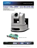


WallVIEW CCU HD-20 HD-SDI
WallVIEW CCU HD-20 HD-SDI Manual 342-0182 Rev. A
Page 13 of 24
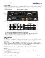
Installation Instructions:
Step 1:
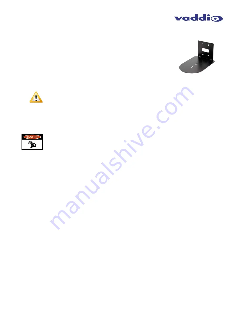
After determining the optimum location of the camera system, route, mark and test
the required two (2) Cat-5e cables and the HD-SDI coax from the camera to the
Quick-Connect CCU Interface located at the head-end. The three Cat-5e cables
should feed-through the oval slot located on the rear flange of the wall mount. If
the bracket is to be mounted on a 2-gang wall box, use the screws supplied with
the wall box cover plate to attach the Thin Profile Wall Mount. If mounting to the
drywall with wall anchors, use four (4) provided drywall anchors. The mounting
holes are slotted and are 90° opposing to provide easy leveling. Level the mount
and tighten down the mounting screws.
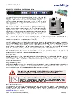
Yet Another Note About the IR OUT Dip Switch 4:
When operating the HD-20 camera with the Quick-Connect CCU, the IR OUT dip switch must be
set to the OFF (up) position on the back of the camera. If it is not turned off, it can and will
interfere with proper operation of the HD-20 PTZ camera which, is never a good deal.
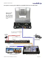
Step 2:
Follow the sample wiring diagram on the previous page for connecting the Cat-5e from the Quick-Connect CCU to
the camera and to the switcher. Additional diagrams are available on our website for installation with other
equipment.
REALLY IMPORTANT NOTE: Check all Cat-5e cables for continuity in advance of the final
connection. Plugging the POWER Cat-5e Cable into the wrong RJ-45 may cause damage to
the camera system and void the warranty.
Step 3:
Place the camera onto the camera mount, connect the previously marked and tested cables to their proper jacks
(please do not guess - especially on the power Cat-5e). Slide the camera back onto the mount, “stuff” the extra
cable back into the wall cavity (dress the cabling) and use the provided ¼” x 20 screws to attach the camera to
the mount securely.
Step 4:
Connect the Vaddio 36 VDC, 2.78A power supply to the Quick-Connect CCU and then the AC side into an AC
outlet. Power will travel down the Power Cat-5e cable to the camera. The camera will “Home” to a centered
position ready for control information from CCU and the camera controller (ProductionVIEW HD or maybe the
Precision Camera Controller). To ensure proper continuity of control and operation of the cameras, the boot order
should be camera first (cameras are always first), the Quick-Connect CCU and lastly, the controller.
Step 5:
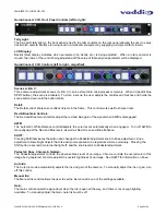
Set-up the CCU:
•
Make sure that the HD video monitor that you are using is set up correctly and is delivering accurate color
reproduction.
•
Adjust the Iris level of the camera so that brighter areas are not washed out.
•
Adjust the Pedestal level so that the black levels are not too dark, and not too light.
•
Adjust the Red & Blue Gain, Gamma, Detail, Knee and Chroma.
NOTE:
Gain (next to Iris) should be left at 0 (zero), unless lighting is inadequate, then turn it to a level where the
signal brightness is at an appropriate level. Gain adds additional noise (grain) to the video the higher it is turned
up.
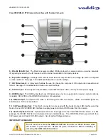
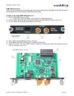
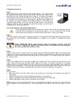
Thin Profile
Camera
Wall Mount


