CeilingVIEW SD CCU
Vaddio CeilingVIEW SD CCU Installation and User Guide - Document 341-769 Rev. A
Page 5 of 16
Figure 5: System Configuration
The main components of the CeilingVIEW SD CCU are the camera module and Quick-Connect CCU and
Quick-Connect CV HD/SD interface. Basic system connectivity is outlined below. The Quick-Connect CV
HD/SD interface can be installed on the optional rack mount adapter, Part # 999-6000-002.
Controlling the Camera
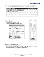
A unique feature of the CeilingVIEW SD CCU allows the camera’s zoom functions (Zoom In and Out) and
intermittent laser (Tilt Down) to be controlled by either a Polycom® or TANDBERG® remote control. In
addition, the Document Camera can be used with either the Vaddio IR remote control supplied or via RS-232
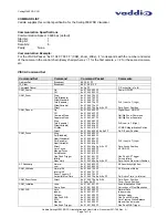
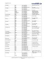
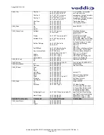
using VISCA control protocol (see VISCA Command Set information at the back of the manual). The
CeilingVIEW SD CCU will respond to all three IR remotes concurrently.
Control Systems
If you are using a control system (i.e. Crestron®, AMX®, etc.) plug the Cat. 5 cable from the RS-232 IN jack
on the camera to your control system using the Cat. 5 to DB-9 serial adapter supplied with the CeilingVIEW
SD. Daisy Chain Note: Use the CeilingVIEW SD as the last camera in the control chain when daisy
chaining cameras together, as there is no RS-232 output on the Camera Module.
SD Video Output
Quick-Connect CV HD/SD
SD Codec
CAT-5
Cables
Up to 400’
Controlled by RS-232,
Vaddio IR Remote and
Polycom IR Remote or
TANDBERG IR Remotes
(zoom and laser pointer)
Video
Adjustments
for Distance
24 VDC
Power
Supply
Power
and
Video
36 VDC
Power
Supply
Optional:
Connection
to external
RS-232
control port
for zoom
control
ProductionVIEW FX
Quick-Connect CCU
CeilingVIEW SD

