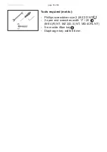
vacuubrand ME 2 NT Скачать руководство пользователя страница 52

page 52 of 88

Fault

Possible cause

Remedy

❑ 

Pump does not 

start or stops im-

mediately.

Electrical power cord 

not plugged in, electri-

cal supply failure?

Plug in power cord. 

Check fuse.

Device fuse blown?

Identify cause of failure. 

Replace device fuse.

Overpressure in outlet 

line or in the system (at 

outlet side)?

Remove blockage in line, 

open valve, or reduce 

overpressure in the sys-

tem (pressure adjustment 

device ME 4R NT).

Motor overloaded?

Allow motor to cool down, 

identify and eliminate 

cause of failure. Manual 

reset is necessary. Switch 

off pump or unplug.

Pump does not 

achieve its ultimate 

vacuum or usual 

pumping speed.

Centring ring at small 

flange connection not 

correctly positioned, or 

leak in the pipeline or 

vacuum system?

Check pump directly - 

connect vacuum gauge 

directly at pump inlet - 

then check connection, 

pipeline and vacuum 

system if necessary.

Vacuum adjustment de-

vice open (ME 4R NT)?

Close vacuum adjustment 

device.

Long, narrow vacuum 

line?

Use lines with larger di-

ameter, length as short as 

possible.

Pump has been ex-

posed to condensate?

Allow pump to run for 

some minutes with atmo-

spheric pressure at the 

inlet to purge.

Deposits have been 

formed inside the 

pump?

Clean and inspect the 

pump heads.

Diaphragms or valves 

damaged?

Replace diaphragms and/

or valves.

Outgassing substances 

or vapor generated in 

the process?

Check process parame-

ters.

Troubleshooting

Содержание ME 2 NT

Страница 1: ...page 1 of 88 Instructions for use Technology for Vacuum Systems Diaphragm pumps ME 2 NT ME 4 NT ME 4S NT MZ 2 NT MZ 2D NT MZ 2S NT ME 8 NT ME 8S NT MD 4 NT MD 4S NT MV 2 NT ME 4R NT MD 4CRL NT ...

Страница 2: ...aphragm pump before leaving our factory is tested intensively including an endurance run of 14 hours Any faults even those which oc cur rarely are identified and can be eliminated immediately After completion of the endurance run every pump is tested and must achieve specifications before shipment We are committed to providing our customers only pumps that meet this high quality standard While our...

Страница 3: ... compris complète ment et seulement si le mode d emploi est observé et tous les mesures demandées sont prises Avis de sécurité pour des dispositifs à vide BG Внимание Тези инструкции не са преведени на всички езици от ЕО Потребителят не бива да работи с уреда ако не разбира инструкциите за ползване В този случай е необходимо да бъде предоставен пълен технически превод на инструкциите за ползване П...

Страница 4: ...ι πλήρως τις οδηγίες αυτές Σε τέτοια περίπτωση ο χρήστης πρέπει να προµηθευτεί ακριßή µετάφραση του ßιßλίου οδηγιών Ο χρήστης πρέπει να διαßάσει και να κατανοήσει πλήρως τις οδηγίες χρήσης και να λάßει όλα τα απαραίτητα µέτρα πριν θέσει σε λειτουργία την συσκευή Υποδείξεις ασφάλειας για αντλίες κενού HR Pažnja ove upute ne postoje na svim jezicima Europske Unije Korisnik nemora raditi sa apara tom...

Страница 5: ...tie Deze gebruiksaanwijzing is niet in alle talen van de EU verkrijgbaar De gebruiker moet niet met dit apparaat gaan werken als voor hem haar de gebruiksaanwijzing niet voldoende dui delijk is Bij gebruik van deze apparatuur is het noodzakelijk een technisch correcte vertaling van de complete gebruiksaanwijzing te hebben Voor het in gebruik nemen van het apparaat moet de gebruiksaanwijzing volled...

Страница 6: ...ruktionen måste läsas och förstås helt före utrustningen tas i drift och nödvändiga åtgärder göres Säkerhetsinformation för vakuumutrustning SI Pozor Ta navodila niso na voljo v vseh jezikih EU Uporabnik ne sme upravljati z napravo če ne razume teh navodil V primeru nerazumljivosti mora biti na voljo tehnično pravilen prevod Navodila se morajo prebrati in razumeti pred uporaba naprave opravljene p...

Страница 7: ...as inlet temperatures 25 Wetted parts 31 Abbreviations 32 Pump parts 33 Use and operation 40 Installation 40 Vacuum connection inlet 40 Connecting the outlet 42 Notes prior to the use of the manometers ME 4R NT 44 Electrical connection 45 During operation 46 Shutdown storage 49 Accessories 51 Troubleshooting 52 Replacing diaphragms and valves 54 Checking diaphragms and valves except MZ 2D NT 57 Re...

Страница 8: ...page 8 of 88 Replacing the fuse 78 Repair Maintenance Return Calibration 80 Warranty 81 Health and safety clearance form 82 EC Declaration of Conformity of the Machinery 83 China RoHS 86 ...

Страница 9: ...rom the pump and the pumped substances VACUUBRAND disclaims any liability for inappropri ate use of these pumps and for damage from failure to follow instructions contained in this manual This manual is only to be used and distributed in its com plete and original form It is strictly the users responsibility to check carefully the validity of this manual with respect to his product Manual no 20901...

Страница 10: ...ts must not be disposed of in the domestic waste at the end of their service life Used electronic devices contain harmful substances that can cause damage to the environment or human health End users are legally obliged to take used electric and electronic devices to a licensed collection point NOTICE Formatting used in this manual Note The signal word panels in all sections of this manual always ...

Страница 11: ...deficiencies Replace the protective caps if the equipment is not used immediately Store the equipment in dry and non corrosive conditions see also Technical data pg 25 Do not use any damaged equipment Use the mounted handle when moving the pump Intended use The vacuum pump may only be used indoors in a dry non explosive atmosphere An attached vapor condenser accessory is exclusively intended for t...

Страница 12: ...se impair safety The use of unauthorized accessories or spare parts Usage despite incomplete assembly operation by insufficiently trained or qualified person nel Switching on off with tools or one s foot Operation with sharp edged objects Pulling plug in connections on the cable out of the socket Extracting or conveying solids or liquids Do not use the pump or any system parts on humans or animals...

Страница 13: ...erature depends on several parameters like inlet pressure and ambient tempera ture see Technical data pg 25 Particles and dust must not enter the pump Do not pump liquids Ensure that the pump is chemically resistant to the pumped substances prior to operation Use the equipment only as intended that is for genera tion of vacuum in vessels designed for that purpose Any other use will automatically i...

Страница 14: ...ure Ensure a stable position of the pump without any me chanical contact other than the pump feet Comply with maximum permissible pressures at in let and outlet and with maximum permissible pres sure differences between inlet and outlet See section Technical data pg 25 Do not operate the pump with overpressure at the inlet Avoid overpressure of more than 17 5 psi absolute 1 2 bar absolute in the e...

Страница 15: ...ting device to separate the pump from the supply voltage Ensure that the mains plug is easily accessible at all times to allow the separation of the device from the power supply Use only hoses at the inlet and outlet of the pump with an inner diameter at least as large as the diameter of the pump s tubing to avoid overpressure at the outlet and reduction of pumping speed at the inlet Allow the equ...

Страница 16: ...detail the conditions under which the equipment can be operated safely see also IP degree of protection Technical data pg 25 Operating conditions These pumps are not approved for operation in po tentially explosive atmospheres Do not operate the pumps in potentially explosive atmospheres Pumps without the mark on the rating plate are not approved for the pumping of potentially explo sive atmospher...

Страница 17: ...to the point of exceeding the maximum permitted temperatures Check the inlet and outlet of the pump if there is a danger of forming deposits inside the pump e g in the pump chambers the pump chamber is the part between diaphragm and head cover See section Re placing diaphragms and valves pg 54 Inspect the pump chambers regularly and clean if necessary Consider interactions and chemical reactions o...

Страница 18: ...losive mixtures at the outlet of the pump or dilute them to non explosive concentrations Never operate this pump if it has a damaged cord or plug If the pump is not working properly has been dropped or has fallen into water contact your pump service pro vider Prevent any part of the human body from coming into contact with vacuum If there is an exhaust isolation valve make sure that you cannot ope...

Страница 19: ...ronment Ensure that no parts of your clothing hair or fingers can be caught or drawn in at the inlet of the pump Never insert fingers or drop any other object into the inlet or outlet Pay attention to the safety symbol hot surfaces on the equipment Hot parts may cause burns if touched Adopt suitable measures to prevent any danger aris ing from hot surfaces or electric sparks Ensure that hot surfac...

Страница 20: ...edures see section Repair Maintenance Return Calibration pg 80 are followed Take advantage of our service seminars which put special focus on the maintenance and repair of vacuum pumps For details and for the online Instructions for repair man ual see www vacuubrand com In normal use the lifetime of the diaphragms and valves is typically 15 000 operating hours Bearings have a typi cal durability o...

Страница 21: ...ven melt or emit a flame which could be dangerous for persons and equipment in the vicinity The capacitors have to be replaced by an electrician Vent the pump before starting maintenance Isolate the pump and other components from the vacuum system Allow sufficient cooling of the pump Drain condensate if applicable Clean polluted surface with a clean slightly moistened cloth To moisten the cloth we...

Страница 22: ...en operating the pump as a compressor check that the system which you are going to pressurize is mechanically stable Check that the maximum gener ated overpressure is compatible with the mechanical stability of the pressure vessel Do not generate over pressure in vessels other than in those designed for that purpose Risk of bursting Comply with maximum permissible pressure at the outlet 58 psi 4 b...

Страница 23: ... explosive atmo spheres caused by gases vapors or mists normally don t occur or if they do occur are likely to do so only infrequently and for a short period only Equipment in this category ensures the requisite level of protection dur ing normal operation The use of gas ballast or the operation of venting valves is only permit ted if thereby explosive atmospheres normally don t occur in the inter...

Страница 24: ...ump achieves its specified ultimate vacuum is the pump s leak rate low enough to en sure that no explosive atmospheres will occur in the interior of the equip ment After any intervention at the vacuum sensor the leak rate of the equip ment has to be checked Attention This manual is not available in all languages of the EU The user must not op erate the device if he does not understand this manual ...

Страница 25: ...protection UL 50E type 1 Pollution degree 2 A weighted emission sound pressure level uncertainty KpA 3 dB A dB A 45 Gas inlet temperatures We reserve the right for technical modification without prior notice Measurement according to EN ISO 2151 2004 and EN ISO 3744 1995 at 230V 50Hz and ulti mate vacuum with silencer at outlet if pumping potentially explosive atmospheres 50 F to 104 F 10 C to 40 C...

Страница 26: ...between inlet and outlet psi bar 29 2 Rated motor power hp kW 0 24 0 18 Maximum permissible range of supply voltage 10 Attention Observe specifications of rating plate Dual voltage motor 100 115 V 50 60 Hz 120V 60 Hz 230 V 50 60 Hz 100 115 V 50 60 Hz 120 V 60 Hz 200 230 V 50 60 Hz Maximum rated current at 100 115 V 50 60 Hz 120 V 60 Hz 200 230 V 50 60 Hz 230 V 50 60 Hz A A A 3 4 1 8 1 8 Inlet hose...

Страница 27: ...Maximum permissible range of supply voltage 10 Attention Observe specifications of rating plate 100 115 V 50 60 Hz 120V 60 Hz 100 V 50 60 120 V 60 Dual voltage motor 230 V 50 60 Hz 100 115 V 50 60 Hz 120 V 60 Hz 200 230 V 50 60 Hz Maximum rated current at 100 V 50 60 Hz 120 V 60 Hz 230 V 50 60 Hz 100 115 V 50 60 Hz 120 V 60 Hz 200 230 V 50 60 Hz A A A A A 1 8 3 4 1 8 5 0 4 0 3 0 5 7 3 0 Inlet smal...

Страница 28: ...ower hp kW 0 34 0 25 Maximum permissible range of supply voltage 10 Attention Observe specifications of rating plate Dual voltage motor 100 115 V 50 60 Hz 120V 60 Hz 230 V 50 60 Hz 100 115 V 50 60 Hz 120 V 60 Hz 200 230 V 50 60 Hz Maximum rated current at 100 115 V 50 60 Hz 120 V 60 Hz 200 230 V 50 60 Hz 230 V 50 60 Hz A A A 5 7 3 0 3 0 Inlet hose nozzle for tubing I D 3 8 hose nozzle DN 10 mm sma...

Страница 29: ...fference between inlet and outlet psi bar 58 4 29 2 Rated motor power hp kW 0 24 0 18 Maximum permissible range of supply voltage 10 Attention Observe specifications of rating plate 100 115 V 50 60 Hz 120 V 60 Hz 230 V 50 60 Hz Maximum rated current at 100 115 V 50 60 Hz 120 V 60 Hz 230 V 50 60 Hz A A 3 4 1 8 Inlet hose nozzle for tubing I D 3 8 hose nozzle DN 10 mm Outlet hose nozzle for tubing I...

Страница 30: ...nlet and outlet psi bar 16 1 1 Leak rate integral Torr cfm mbar l s 0 0016 0 001 Rated motor power hp kW 0 34 0 25 Maximum permissible range of supply voltage 10 Attention Observe specifications of rating plate 100 115 V 50 60 Hz 120 V 60 Hz 200 230 V 50 60 Hz Maximum rated current at 100 115 V 50 60 Hz 120 V 60 Hz 200 230 V 50 60 Hz A A 5 7 3 0 Inlet small flange KF 16 Outlet small flange KF 16 D...

Страница 31: ...NT FFKM Valves ME 4R NT PTFE O rings FPM Connection tube aluminum alloy AlMgSi0 5 Small flange stainless steel Hose nozzle PBT Hose nozzle ME 4 NT ME 4S NT stainless steel Silencer PA PE aluminium or aluminum alloy silicone Fittings ME 4 NT ME 4R NT ME 4S NT MZ 2 NT MZ 2S NT MZ 2D NT aluminum anodized Tubing ME 4 R NT MZ 2 NT MZ 2D NT PE Tubing ME 4S NT MZ 2S NT PTFE Seal rings ME 4 NT ME 4R NT ME...

Страница 32: ...tment device ME 4R NT O ring NBR Valve block aluminum alloy Seal ring at manometer copper Hollow bolt dispensing screw stainless steel Overpressure safety relief device FPM Abbreviations ETFE Ethylene Tetrafluoroethylene FFKM Perfluoro elastomer FPM Fluoroelastomer NBR Nitrile butadiene rubber PA Polyamide PBT Polybutylene terephthalate PE Polyethylene PTFE Polytetrafluoroethylene PVC Polyvinyl ch...

Страница 33: ...8 Inlet with vacuum adjustment device 9 Outlet with pressure adjustment device 10 Dispensing screw 11 Overpressure manometer 12 Vacuometer 13 Overpressure safety relief device 14 Voltage selection switch We reserve the right for technical modification without prior notice Pump parts 4 7 Power connection all pump designs ...

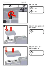
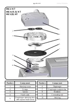
Страница 34: ...page 34 of 88 ME 4 NT 1 5 3 2 6 4 ME 4 NT ME 4S NT 1 5 3 2 6 4 fig ME 4 NT ...

Страница 35: ...page 35 of 88 ME 4R NT 9 5 3 6 12 8 10 11 10 4 13 MZ 2 NT MZ 2S NT fig MZ 2 NT 5 3 2 6 4 1 ...

Страница 36: ...page 36 of 88 MZ 2D NT 5 3 2 6 4 ME 8 NT ME 8S NT 2 5 3 2 6 4 1 1 ...

Страница 37: ...page 37 of 88 6 MD 4 NT MV 2 NT fig MD 4 NT 1 5 3 4 2 7 MV 2 NT 1 5 3 4 2 7 6 14 MD 4S NT ...

Страница 38: ...page 38 of 88 MD 4CRL NT 5 3 2 7 6 14 4 1 ...

Страница 39: ...20 corresponds to 100 120 V and 230 240 corresponds to 200 230 V Check that the voltage selection switch is posi tioned correctly Note If the pump is switched on with wrong volt age selection the motor may be damaged Check every time before starting the pump Change the selection at the voltage selection switch only if the pump is unplugged from the power source Only pumps with dual voltage motor ...

Страница 40: ...ciona a Vácuo Instrucţiuni de siguranţă pentru aparatele de vidare Указания по технике безопасности при работе с вакуумными устройствами Säkerhetsinformation för vakuumutrustning Varnostni nasveti za vakuumske naprave Bezpečnostné pokyny pre vákuové zariadenia Vakumlu cihazlar için güvenlik uyarıları DE EN FR BG CN CZ DA EE ES FI GR HR HU IT JP KR LT LV NL PL PT RO RU SE SI SK TR Remove the produc...

Страница 41: ...ter and keep them as short as possible to avoid flow losses Locate the pump as closely as possi ble to the application NOTICE Particles and dust must not be aspirated If necessary you must install appropriate filters You must ensure their suitability concerning gas flow chemical resis tance and resistance to clogging prior to use A power failure may cause accidental ventilation of the pump If this...

Страница 42: ... G1 4 NOTICE outlet If dangerous or polluting fluids could be released at the outlet install an appropriate system to catch and dispose of those fluids Connect a gas tight exhaust line at the pump outlet nozzle and secure against loosen ing for example with a hose clamp Always vent exhaust gases appropriately e g into a fume hood In case replace silencer with hose nozzle see above MD 4CRL NT Conne...

Страница 43: ...ump as vacu um pump provide a free and pressureless exhaust outlet to avoid damage to pump valves and risk of bursting Reduce the transmission of vibration Prevent mechan ical load due to rigid pipelines Insert elastic hoses or flexible elements as couplings between the pump and rigid pipes Secure hose connections at the pump ap propriately e g with hose clamps to protect against accidental detach...

Страница 44: ...re installed at the pump and proceed according to the given instructions A Manometer with bore at the rear side Pierce the hole at the rear side of the mano meter Some outflow of liquid is normal Do not tilt pump during transport B Manometer with pin Lift the pin to vent the manometer Do not re move the pin completely Close after venting Repeat if necessary until the dial shows ATM with the measur...

Страница 45: ...e phase and frequency Check that the voltage selection switch is positioned correctly Check every time be fore starting the pump Note If the pump is switched on with wrong voltage selection the motor may be damaged Changing the selection at the voltage se lection switch Change the selection at the voltage se lection switch only if the pump is un plugged from the power source 1 Disconnect the elect...

Страница 46: ...f install ing the pump in a cabinet or a housing Make sure ventilation is adequate especial ly if the ambient temperature is elevated Operation with silencer at the outlet Oper ating the pump at a high inlet pressure or pumping dusty gases for a long time may cause clogging of the silencer Check the silencer regularly and replace if necessary or install a hose nozzle with sealing ring in stead see...

Страница 47: ...E 4R NT Note There are no stops at the end of the dispensing screws threads Do not com pletely unscrew the dispensing screws Do not start the pump if the pressure difference between inlet and outlet ports exceeds max 16 0 psi 1 1 bar Attempts to start the pump at higher pressure difference may cause stalling and damage of the motor NOTICE Prevent internal condensation transfer of liq uids or dust ...

Страница 48: ...ufficiently before restart C F I O 3 2 1 NOTICE Note In case of supply voltage below 100V the lock of the breaker may not latch and the pump might re start on its own after sufficient cooling Take appropri ate precautions if an automatic restart of the pump may lead to a dangerous situation air Make sure the fan s air supply is adequate Check fan regularly for dust dirt Clean fan guard grill if ne...

Страница 49: ...he pump to control the overpres sure accordingly Turning the dispensing screw counterclock wise pressure is decreased Pump blows off via dispensing screw Turning the dispensing screw clockwise pressure is increased Note Maximum permissible overpressure at the outlet side of the ME 4R NT pump 44 psi 3 bar Shutdown storage The pump can be switched off under vacuum Condensate O I 5 10min atm Short te...

Страница 50: ...88 Long term Take measures as described above regard ing short term shutdown Separate the pump from the application Close inlet and outlet ports e g with trans port caps Store the pump under dry conditions NOTICE ...

Страница 51: ...ternal thread G 1 8 stainless steel 20639758 Sealing ring for hose nozzle 639758 20639729 Silencer for hose nozzle 3 8 DN 10 mm 20636588 For additional accessories such as vacuum valves small flange components vacuum gauges or vacuum controllers refer to www vacuubrand com Vacuum gauge DVR 2pro 20682906 Attention Dust laden gases deposits and condensed solvent vapor can restrict air flow out the s...

Страница 52: ...ate vacuum or usual pumping speed Centring ring at small flange connection not correctly positioned or leak in the pipeline or vacuum system Check pump directly connect vacuum gauge directly at pump inlet then check connection pipeline and vacuum system if necessary Vacuum adjustment de vice open ME 4R NT Close vacuum adjustment device Long narrow vacuum line Use lines with larger di ameter length...

Страница 53: ...essure especially with condensable vapors Diaphragm crack or diaphragm clamping disc loose Perform maintenance Other than above men tioned causes Contact local distributor Pump seized Contact local distributor A service manual with exploded view drawings spare parts list and directions for repair is available on request The service manual is intended for trained service people only ...

Страница 54: ... with the pro cess chemicals that have been pumped during opera tion Ensure that the pump is decontaminated before maintenance Avoid the release of pollutants Never operate a defective or damaged pump Check every motor capacitor regularly by measuring its capacity and estimating its service life Replace old capacitors early enough to prevent a failure The ca pacitors must be replaced by a trained ...

Страница 55: ... vacuum is no longer achieved or in case of increased noise level the pump interior the diaphragms and the valves must be cleaned and the diaphragms and valves must be checked for cracks or other damage All bearings are encapsulated and are filled with long life lubricant Under normal operating conditions the drive system is maintenance free In demanding circumstances it may be efficient to check ...

Страница 56: ...page 56 of 88 Tools required metric Phillips screwdriver size 2 MZ 2D NT 2 open end wrenches width 17 20 ME 4 R NT MZ 2 D S NT MD 4CRL NT 5 mm wide Allen key Diaphragm key width 66 mm ...

Страница 57: ...page 57 of 88 Checking diaphragms and valves except MZ 2D NT 1 20 17 2 20 17 1A 20 17 ME 4R NT ME 4R NT ME 4 S NT MZ 2 S NT 17 mm 20 mm 17 mm 20 mm 17 mm 20 mm ...

Страница 58: ...page 58 of 88 1B 20 17 3 3A MD 4CRL NT 5 4x ME 2 NT ME 4 R S NT MZ 2 S NT 5 8x ME 8 NT MV 2 NT MD 4 S CRL NT 17 mm 20 mm ...

Страница 59: ...E 2 NT ME 4 R S NT MZ 2 S NT Position Component 6 Diaphragm 7 Diaphragm support disc 8 Washers 9 Connecting rod 10 Housing Position Component 1 Housing cover 2 O rings 3 Valves 4 Head cover 5 Diaphragm clamping disc with square head screw ...

Страница 60: ... Component 1 Housing cover 2 O rings not ME 8 NT 3 Valves 4 Head cover 5 Diaphragm clamping disc with square head screw 6 Diaphragm Position Component 7 Diaphragm support disc 8 Washers 9 Connecting rod 10 Housing 11 Connecting tube with O ring MD 4CRL NT with screw in fitting ...

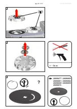
Страница 61: ...page 61 of 88 4 5 6 Clean 20696877 20696860 20696861 20696862 20696868 20696859 20696870 ...

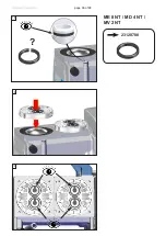
Страница 62: ...page 62 of 88 7 8 9 1 2 ...

Страница 63: ...UBRANDCXXX VACUUBRAND VACUUBRANDCXXX VACUUBRAND 11 11A Pay attention to washers Assemble same number and thick ness 1x 2x ME 2 NT ME 4 NT MZ 2 NT ME 8 NT MD 4 NT MV 2 NT ME 4S NT MZ 2S NT ME 8S NT ME 4R NT MD 4S NT MD 4CRL NT ...

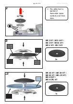
Страница 64: ...page 64 of 88 12 13 14 Pay attention to washers Assemble same number and thick ness ...

Страница 65: ...acing the valves and assembling the pump heads 1 2 15 4 4 ft lbf 6 Nm It is recommended to use a torque wrench Attach torque wrench to diaphragm key hexagonal bolt 6 mm wide 16 17 ME 8 NT MD 4 NT MV 2 NT except MZ 2D NT ...

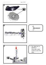
Страница 66: ...page 66 of 88 18 19 20 23120788 ME 8 NT MD 4 NT MV 2 NT ...

Страница 67: ...page 67 of 88 21 22 23 ...

Страница 68: ... the same way 5 8x A 1 8 1 4 hand tight B 1 8 1 4 8 9 ft lbf 12 Nm 4x ME 2 NT ME 4 R S NT MZ 2 S NT 1 4 ME 8 NT MV 2 NT MD 4 S CRL NT 1 8 26 20 17 Assembling the connecting hose ME 4 R S NT MZ 2 S NT MD 4CRL NT ME 4R NT 5 2 8 4 1 7 3 6 17 mm 20 mm ...

Страница 69: ...page 69 of 88 27 20 17 26A 20 17 26B 20 17 ME 4R NT ME 4 S NT MZ 2 S NT MD 4CRL NT 17 mm 20 mm 17 mm 20 mm 17 mm 20 mm ...

Страница 70: ...page 70 of 88 1 20 17 2 3 Checking diaphragms and valves MZ 2D NT 5 4x 17 mm 20 mm ...

Страница 71: ...9 10 11 1 2 5 7 8 Position Component 1 Housing cover 2 O rings 3 Valves 4 Head cover 5 Diaphragm clamping disc 6 Countersunk head screw Position Component 7 Diaphragm 8 Diaphragm support disc 9 Washers 10 Connecting rod 11 Housing ...

Страница 72: ...page 72 of 88 6 4 5 Clean 20696863 size 2 1x Pay attention to washers Assemble same number and thickness Remove adhe sive residues replace if nec essary 20639847 ...

Страница 73: ...RANDCXXX VACUUBRAND VACUUBRANDCXXX VACUUBRAND 8 9 Pay attention to washers Assemble same number and thick ness 2x Adhesive OmniFit 50M or Loctite 243 OmniFit and Loctite are regis tered trade marks of Henkel Tech nologies 2x ...

Страница 74: ...page 74 of 88 10 size 2 1x Replacing the valves and assembling the pump heads MZ 2D NT 11 12 ...

Страница 75: ...page 75 of 88 13 14 15 ...

Страница 76: ...page 76 of 88 16 17 18 Maintain all pump heads in the same way 5 4x A 1 4 hand tight B 1 4 8 9 ft lbf 12 Nm 1 2 3 4 ...

Страница 77: ...acuum In case of an unusual noise switch off pump immediately and check clamping disc positions If the specified ultimate vacuum is not achieved and if this does not change after the break in period Check hose connectors at pump heads for leaks If necessary recheck valve seats and pump chambers Checking the ultimate vacuum After any intervention at the equipment e g repair maintenance the ultimate...

Страница 78: ... off the pump Disconnect the electrical power cord before open ing the terminal box After disconnecting from power wait five seconds to allow the capacitors to discharge The replacing of the fuse has to be carried out by a trained electrician After replacing the fuse the pump must be checked for electric safety see below Identify and eliminate the cause of failure before switching on the pump agai...

Страница 79: ...ng the device fuse Check the electrical safety protective conductor resis tance insulating resistance high voltage test accord ing to IEC 61010 and national regulations 3 T20 4x Remove both wires with integrated fuses fixed with flat pin bushings 2 see figure Mount the new wires flat pin bushings ...

Страница 80: ...ditions apply to on site work No repair maintenance return or calibration is possible unless the correctly completed health and safety clearance form is returned Devices sent are rejected if applicable Send a completed copy of the health and safety clearance form to us in advance The declaration must arrive before the equipment Enclose a second completed copy with the product Remove all components...

Страница 81: ...l re quirements Particular care must be taken with components and waste oil which have been contaminated with dangerous substances from your processes Do not incinerate fluoroelastomer seals and O rings You may authorize us to dispose of the equipment at your expense Otherwise we return the device at your expense VACUUBRAND shall be liable for insuring that this product including any agreed instal...

Страница 82: ... for reason of appearance repaint and replacement at customer s expense yes no 12 Legally binding declaration We assure for the returned device that all substances which have been in contact with the device are listed in section 5 and that the information is complete and that we have not withheld any information We declare that all measures where applicable have been taken listed in section Repair...

Страница 83: ...22614371 20736105 20736445 20738000 20738001 20738002 22614251 Seriennummer Serial number Numéro de série Siehe Typenschild See rating plate Voir plaque signalétique Angewandte harmonisierte Normen Harmonized standards applied Normes harmonisées utilisées DIN EN ISO 12100 2011 DIN EN 61010 1 2011 IEC 61010 1 2010 Ed 3 DIN EN 1012 2 2011 DIN EN 1127 1 2011 DIN EN 13463 1 2009 DIN EN 50581 2013 Bevo...

Страница 84: ...ir plaque signalétique Angewandte harmonisierte Normen Harmonized standards applied Normes harmonisées utilisées DIN EN ISO 12100 2011 DIN EN 61010 1 2011 IEC 61010 1 2010 Ed 3 DIN EN 1012 2 2011 DIN EN 50581 2013 Bevollmächtigter für die Zusammenstellung der technischen Unterlagen Person authorized to compile the technical file Personne autorisée à constituer le dossier technique Dr J Dirscherl V...

Страница 85: ...page 85 of 88 This certificate is only valid for pumps with the respec tive mark Licensed Test mark on the pump rating plate ...

Страница 86: ...during which the hazardous substances contained in electrical and electronic products will not leak or mutate under normal operating conditions During normal use by the user such electrical and electronic products will not result in serious environmental pollution cause serious bodily injury or damage to the user s assets The Environmentally Friendly Use Period for VACUUBRAND products is 40 years ...

Страница 87: ...有意用铅 Pb 汞 Hg 铬 Cd 六价铬 Cr VI 多溴联苯 PBB 或多溴二苯醚 PBDE 来制造的 Apart from the disclosures in the above table the subassemblies are not intentionally manufactured or formulated with lead Pb mercury Hg cadmium Cd hexavalent chromium Cr VI polybrominated biphenyls PBB and polybrominated diphenyl ethers PBDE Products manufactured by VACUUBRAND may enter into further devices e g rotary evaporator or can be used...

Страница 88: ...fore strictly the users responsibil ity to very carefully check the application of these data to their specific requirements No claims arising from the information provided in this lit erature will consequently be entertained Alfred Zippe Str 4 97877 Wertheim Germany T 49 9342 808 0 F 49 9342 808 5555 info vacuubrand com www vacuubrand com VACUUBRAND GMBH CO KG Technology for Vacuum Systems 2021 V...

Отзывы: