PC
BOARDS
Service Manual M4 - M10
22.10.2001
Page
98
9.4 Adapter board
9.4.1 Description
Adapter board is the part of the control circuitry, where feedback of the actual
output current of the drive is measured/attenuated for the usage of motor
control. The output current is measured from each three output phases
individually for accurate feedback for motor control and to detect common
mode current caused by ground fault in output circuitry. The current is
measured by hall element based current transducers (CT), from where signal
is lead to resistor network. By the resistor network the current signal from
the CT is adapted to measuring circuit to generate correct signal level at
nominal point of load current. Proportional current signal is converted to
voltage signal for the further processions. The CT modules are placed either
on the Adapter board or mounted on chassis of the drive.
Resistors in current measurement circuitry for type of the drive related
settings are placed on the board. The resistor settings are specified on chart
CX2ADAP.XLS, CX4ADAP.XLS and CX6ADAP.XLS and described in section 17
Precharging resistor(s) is placed on the board.
9.4.2 Warnings
The Adapter board is connected to DC bus bus and carries dangerous
energies. Any time if intended to be performed testing or repair, make sure
that techniques which are going to be used complies with general safe
working instructions. Make sure that equipments used for the tests are
designed to voltage levels which can exist in circuit.
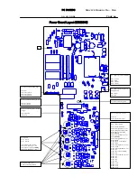
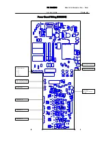
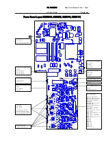
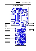
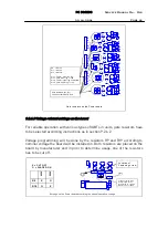
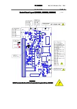
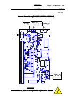
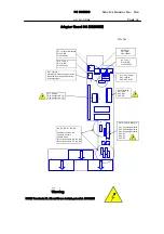
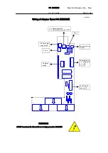
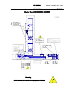
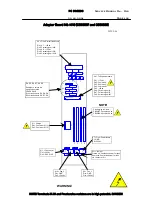
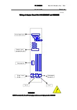
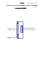
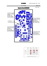
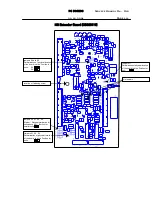
9.4.3 Layout, connectors and wirings
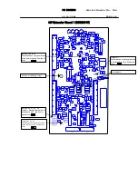
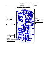
Layout drawings, connector and wirings of the Adapter boards are illustrated
on following pages.
Содержание CX
Страница 1: ......
Страница 33: ...TROUBLESHOOTING Service Manual M4 M10 11 07 2002 Page 33 ...
Страница 34: ...TROUBLESHOOTING Service Manual M4 M10 11 07 2002 Page 34 ...
Страница 148: ...SPARE PART LISTS Service Manual M4 M10 Page 148 ...

