14
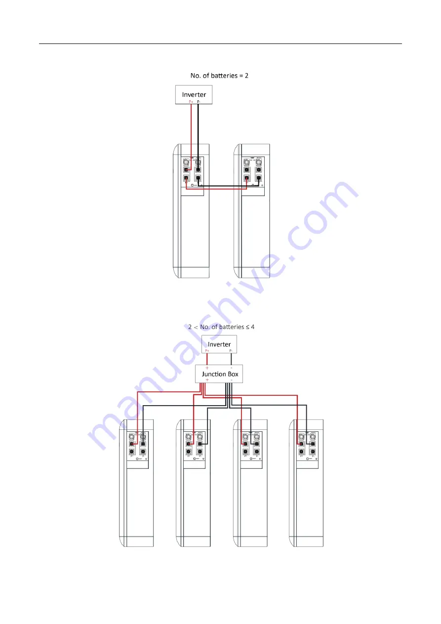
Figure 11. Connect the power cables (Battery=2)
Figure 12. Connect the power cables (2 < Batteries ≤ 4)
Страница 1: ...RESIDENTIAL ESS LITHIUM ION BATTERY SOLUTION VE51280W...
Страница 2: ...ith a high level of risk which if not avoided will result in death or serious injury Warning Indicates a hazard with a medium level of risk which if not avoided could result in death or serious injury...
Страница 3: ...nstallation 8 2 2 1 Tools 8 2 2 2 Packing List 9 2 2 3 Unpacking Acceptance 10 2 3 Installing Guide 10 2 4 Connecting Power Cable 12 2 5 Connecting Communication Cable 15 3 Operation 19 3 1 Check befo...
Страница 4: ...extend battery life it has multiple protection functions such as system over charge system over discharge cell over voltage cell under voltage charging over current discharging over current and insula...
Страница 5: ...2 Figure 2 V Power S14 dimensions unit mm 1 3 Panel Introduction The V Power S14 operation panel is shown as follows Figure 3 V Power S14 operation panel...
Страница 6: ...5 GND Grounding 6 POWER Power switch 7 Base Mounting base The SOC indicator used to identify the current capacity status of V Power S14 The number of blinking indicators corresponds to different remai...
Страница 7: ...ance 1 4 PIN Definition V Power S14 has 2 communication interfaces COM1 and COM2 the PIN definition of COM ports are shown as follows Table 4 The Communication Port Definition COM1 2 Pin Description C...
Страница 8: ...pollution free features Lithium ion cell s three views are shown as follows Figure 4 Lithium ion cell three views unit mm Lithium ion cell main technical specifications are shown as follows Table 5 Li...
Страница 9: ...shown as follows Table 6 V Power S14 technical specifications No Items Parameter 1 Model VE51280W 2 The number of cells 16 3 Configuration 1P16S 4 Nominal voltage 51 2 V 5 Nominal capacity 280 Ah 6 T...
Страница 10: ...5 mm 801 mm 251 mm without base 24 Net weight Approx 121 kg Protection function 25 Over voltage protection System over voltage cell over voltage 26 Under voltage protection System under voltage cell u...
Страница 11: ...two people must work together one operating and the other inspecting The original cable connection and operation process shall not change without the authorization of the company s consent 2 2 Prepar...
Страница 12: ...ltimeter Anti static gloves Helmet Goggle Insulation shoes Insulating tape 2 2 2 Packing List Open the package and take out the product please check the accessories rst The packing is shown below Figu...
Страница 13: ...firm receipt and indicate the extent of the damage If the damage of the packing box is serious please refuse to sign Please carry out an unpacking inspection after receiving all the goods If users fin...
Страница 14: ...e Figure 6 Installing V Power S14 3 Using a drill and level mount the base to the selected wall Check whether the bolt torque of the nuts 2 nuts on the back of V Power S14 is 8 N m Mount the V Power S...
Страница 15: ...box to the inverter The V Power S14 power cable connection method adopts a self locking connector The description of the self locking connector is shown as follows The steps for connecting the self l...
Страница 16: ...Figure 10 Connect the external cables If there are multiple V Power S14 in parallel you need to connect them in parallel using the parallel power cables then connect the power cable to the inverter Pl...
Страница 17: ...14 Figure 11 Connect the power cables Battery 2 Figure 12 Connect the power cables 2 Batteries 4...
Страница 18: ...orresponds to the negative pole Please take care of the removed V Power S14 protective cover in case of backup 2 5 Connecting Communication Cable Context Please pay attention to the direction when plu...
Страница 19: ...here are multiple V Power S14 in parallel you need to connect the communication cables in parallel first Then connect the communication cable between the inverter and COM1 of the first V Power S14 Fig...
Страница 20: ...17 Figure 16 Connect the communication cables 2 Batteries 4 Figure 17 Connect the communication cables 4 Batteries 8...
Страница 21: ...user manual of inverter The communication cable to the inverter contains L N cable 220V power supply for BMS Please connect this cable to the output port of the inverter Optional Recommended open cir...
Страница 22: ...ayout diagram 2 Check the cable connection on site Check whether the cables are connected correctly whether the connectors are firm and whether the self locking connector is tightly connected Check wh...
Страница 23: ...power on is divided into three categories 1 Single battery power on no parallel connection Turn on the DC switch of inverter Turn on the switch between the inverter and power grid Turn on the circuit...
Страница 24: ...ty is above 50 Turn on the ON OFF switch of one new expansion battery at this time the battery Run Alarm indicator light should be blinking green Wait for the battery Run Alarm indicator lights from g...
Страница 25: ...e recommended storage temperature is 15 35 V Power S14 performance degradation after long term storage please shorten shelf time as possible as you can Charge before using to recover capacity loss of...
Страница 26: ...er S14 Please contact Vestwoods in time for other abnormal situations Operation environment The operation environment is between 0 45 Operation humidity range 95 RH If temperature and humidity are abn...
Страница 27: ...arging the battery under temperature alarm is generated If battery temperature 20 while the battery is discharging the battery under temperature alarm is generated Alarm recover When the cell temperat...
Страница 28: ...25 Acronyms and Abbreviations AC Alternating Current BMS Battery Management System DC Direct Current SOC State of Charge...