background image

The Utile Engineering Co. Ltd.

28/07/04

Irthlingborough, Northamptonshire. England
Tel: +44 (0) 1933 650216
Fax: +44 (0) 1933 652738

6

IC101

Handling

Skilled personnel working in accordance with safe working practices
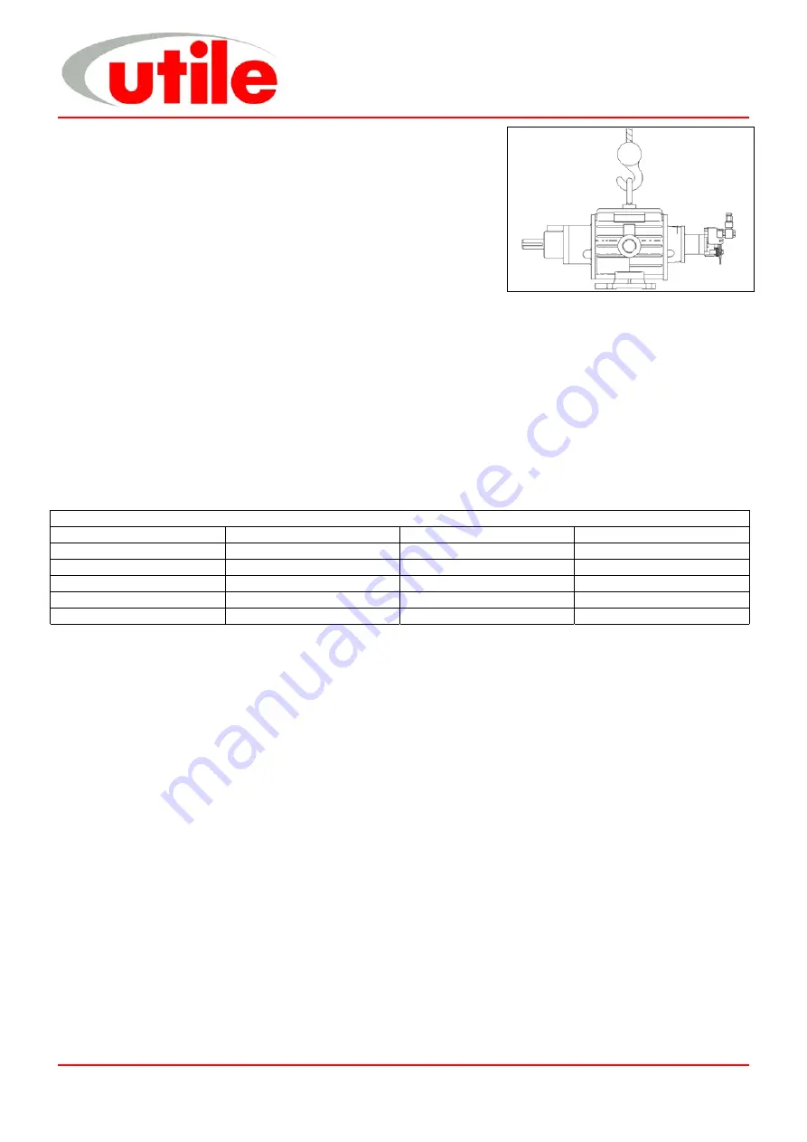
must carry out the lifting of machines. Before lifting the correct
equipment must be available. Cranes, jacks, slings, and lifting beams
must be capable of carrying the weight of the machine to be lifted. The
lifting eyebolt situated in the top of the cylinder and a crane hook must
be used when lifting or moving the machine (see fig 3). Do not use the
machine ports or the shaft extension for lifting or moving the machine.

For weights see above in Technical Specification.

Installation

Utile Engineering trained personnel or those trained to an equivalent standard should carry out installation, any
claims for damage due to faulty installation will be void. The machine is delivered ready to be connected, with only
the removal of the intake and discharge protection covers. All warning labels and instructions must be observed
and retained with the machine. Before installation, ensure there is no damage to the machine and that it turns
freely by hand.

Typical tools required for installation include: -
Set of spanners

Pipe Wrenches

Set of screwdrivers

Hacksaw

Hammer / mallet

Typical bolt tightening torques are: -

Bolt Tightening Torques

Size

Torque

Size

Torque

M4

1.75 Nm

M12

50.00 Nm

M5

3.50 Nm

M16

100.00 Nm

M6

6.00 Nm

M20

150.00 Nm

M8

15.00 Nm

M24

250.00 Nm

M10

30.00 Nm

Location

The machine should be installed in a clean, dry, well-ventilated area. Allow adequate space and facilities for
service, inspection and future expansion. A minimum of 0.75m of working space around the machine is
recommended. Adequate space around the motor and machine, particularly any fan inlets, is also necessary to
facilitate cooling airflow. Where several machines are installed in close proximity, care must be taken to ensure
there is no recirculation of exhausted warm air.

Foundation

Simple slab type foundations, designed for static loadings only are satisfactory. The foundations should raise the
machine to a reasonable height above the floor for convenient service and inspection. The use of anti-vibration
mounts between the base and foundation are recommended, these absorb the vibrations generated by the rotating
parts of the machine and insulate it against any vibration in the surrounding environment. Ensure that the anti-
vibration mounts are evenly loaded. Foundation bolts should fix the base.

Electrical Supply and Connection

The voltage rating of the supply must be compatible with the motor and the fittings. All electrical installation must be
carried out by a qualified electrician and in accordance with current regulations and within the framework of the
Electricity of Work Regulation 1990. Ensure all electrical connections, plugs, sockets etc are secure before
switching the supply on.

Earthing

It is important that the motor enclosure is soundly earthed by metallic earth continuity conductor, or by separate
earth bonding, but in all cases the installation must be made and tested and approved for this feature by a qualified
installer before the supply is applied to the motor.

Handling
Installation

Fig. 3

Содержание LGA12

Страница 1: ...Ltd 28 07 04 Irthlingborough Northamptonshire England Tel 44 0 1933 650216 Fax 44 0 1933 652738 1 IC101 Installation Operation Maintenance Instructions Model LGA12 26 Gas Compressor Serial Number Site Location Installation Date ...

Страница 2: ...pment into which the machine has been incorporated and the said equipment declared to be in conformity with the Machinery Directive they must not be put into service Foreword The LGA series rotary gas compressor has been developed based on many years of experience in the compressor and vacuum pump industry Using modern design techniques and production methods coupled with rigorous testing and high...

Страница 3: ...k on the displacement principle They provide a constant low pulsation supply of air or gas The machines have a cylindrical bored housing The rotor which is also cylindrical is fitted eccentrically in the cylinder so that a crescent shaped working chamber is formed Movable rotor vanes are fitted in the longitudinal grooves in the rotor centrifugal force and the force of the air or gas presses the b...

Страница 4: ...rgency stop buttons and other such devices if fitted are to be checked regularly to ensure that they continue to function correctly and will protect the installation and personnel in the event of an emergency NO attempt should be made to touch the machine whilst it is rotating Particular care is needed when checking rotor clearances Any movement of rotors may trap fingers Most machines certain pip...

Страница 5: ...r general protection The ancillary components are packed suitably within the case The packaging and contents should be received in good condition When unpacking do not remove the inlet outlet protection covers The contents should be inspected against the advice note notify Utile Engineering within 3 days of any items which are damaged or are missing followed by a written claim within seven days of...

Страница 6: ...e installed in a clean dry well ventilated area Allow adequate space and facilities for service inspection and future expansion A minimum of 0 75m of working space around the machine is recommended Adequate space around the motor and machine particularly any fan inlets is also necessary to facilitate cooling airflow Where several machines are installed in close proximity care must be taken to ensu...

Страница 7: ... parallel alignment see fig 5 Place a straight edge across the coupling The hubs will be in correct alignment when the straight edge contacts the 4 points squarely Drive Belts 1 Remove any dirt oil etc from all mating surfaces Place bush in hub and match half holes on both shafts 2 Mount assembly in desired position on shafts ensuring both shafts are parallel and in correct alignment use a straigh...

Страница 8: ...ve belts removed 9 Recheck coupling drive alignment and retension see page 7 9 Ensure all equipment is installed and earthed in accordance with current legislation 9 Check all piping connections 9 If the system is to be pressure tested all gauges and pressure switches must be isolated or removed Maximum purge or pressure test is 1 50 times the working pressure 9 Check all protective devices ensuri...

Страница 9: ...djusted to the correct flow rate when despatched from our works If it found necessary to alter the oil feed then proceed as follows using fig 7 1 Remove the cover 1 to expose two pistons 2 2 Slacken off the locknuts 3 and adjust the feed as required To increase the flow turn the two adjusting screws 4 clockwise or anti clockwise to decrease Lubricator Maintenance Refill the oil reservoir regularly...

Страница 10: ...be replaced after 15000 operating hours or 2 years whichever is sooner Blades must be replaced regardless of wear after 20000 operating hours as failure due to fatigue could cause serious damage After maintenance the machine and equipment must be treated as new and all pre commissioning checks should be made Install all protective devices and controls properly after completion of work Ensure all c...

Страница 11: ...perature excessive 4 Warped Sticking blades 4 Replace blades 1 Insufficient lubricant to cylinder 1 Inspect clean oil lines oil holes 2 Incorrect lubricant 2 Use correct lubricant 3 Dirty inlet air gas 3 Clean inspect intake Excessive blade wear 4 Excessive operating temperature 4 See remedies for excessive discharge temperature 1 Worn bearing 1 Replace bearing 2 Excessive blade wear 2 Replace bla...

Страница 12: ...s recommended but if work has to be carried out on site we advise you most strongly to contact Utile Engineering Service Department for advice During inspection determine if the correct oil is being used Bearings cylinder wall rotor shaft assembly and blades should show a polished surface with a light film of oil Hard baked deposits indicate inferior oil dirt or excessive temperature 3 Reassembly ...

Страница 13: ... 0 08mm Rear End Coverplate Rotor 0 13mm 0 15mm 0 13mm 0 15mm 0 13mm 0 15mm Rotor Cylinder 0 08mm 0 10mm 0 08mm 0 10mm 0 08mm 0 10mm Reassembly should start with the preparing of the rotor and shaft assembly by the fitting of the replacement seal sleeve if required and the inner races of the both roller bearings 6 1 The seal sleeve 8 are retained on the clean shaft using LOCTITE 648 adhesive or eq...

Страница 14: ... by hand before refitting oil pipes Prime oil pipes before use 7 Spare Parts A stock of the main wearing parts at the installation site is important to the constant availability and smooth running of the machine We recommend the following parts and quantities to be kept in stock at the installation site Part Number Description LGA12 LGA18 LGA26 Quantity Blade S 8331 1 S 8331 2 S 8331 3 6 Ball Bear...

Страница 15: ...F 1200 1 14 BEARING SEAL R E F 1047 V F 1047 V F 1047 V 1 15 THRUST WASHER B 1057 B 1057 B 1057 1 16 MECHANICAL SEAL F 1115 F 1115 F 1115 1 17 LOCK NUT B 1073 B 1073 B 1073 1 18 TAB WASHER B 1074 B 1074 B 1074 1 19 CIRCLIP B 1033 B 1033 B 1033 2 20 SOCKET HEAD CAP SCREW G 1060 K 1062 K 1062 12 21 HEX HEAD SCREW G 1030 G 1030 G 1030 4 22 SOCKET HEAD CAP SCREW G 1048 G 1048 G 1048 3 23 DOWEL PIN E 1...

Страница 16: ...defect are incurred 2 Malfunction caused by fair wear and tear abnormal conditions of use accident neglect or misuse of equipment or improper storage 3 Deviation from operating specifications or other special terms of sale 4 Improper operation maintenance or repair 5 Damage resulting during shipment or installation by other than company authorised personnel 6 Freight charges for goods returned to ...

Отзывы: