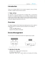
User Manual
CP2-300
4
configuration time is about 5s), reset to factory defaults by pressing in 15s.
LAN1/POE Port: PoE port for handling all user traffic and powering the device. The
port is used as the LAN port under bridge mode, and as WAN port under gateway mode.
LAN2 Port: For handling all user traffic, could connect with PC, cameras and switches.
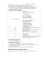
2. LED Indicator Instruction
SIG1, SIG2, SIG3, SIG4
Signal Indicator:
Master AP: Output Power Indicator
<
25% (SIG1 ON)
25%~50% (SIG1-SIG2 ON),
50%~75% (SIG1-SIG3 ON),
75%~100% (SIG1-SIG4 ON).
Slave AP: Signal Strength Indicator
Failure Connection: Flowing
Successful Connection:
0~-65dBm (SIG1-SIG4 ON),
-66~-75dBm (SIG1-SIG3 ON),
-76~-85dBm (SIG1-SIG2 ON),
≤ -86dBm (SIG1 ON).
LAN1
Connected and data is under transmission (Flicker)
Disconnection (OFF)
LAN2
Connected and data is under transmission (Flicker)
Disconnection (OFF)
The device is under normal operation (Flicker)
Power ON (ON)
Power OFF (OFF)
Digital Switch / Reset: Value 1 would be added by short
pressing (Value Circulation: 0-9-A-C)
3. Pairing Configuration
(1) One-to-one Pairing
①
Configure one to bridge access point, and the other one to bridge client.
②
Short pressing the
“Digital Switch / Reset”, Value 1 would be added by short
pressing (Value Circulation: 0-9-A-C).
③
Set the same channel value for both two devices, then finished the pairing.
(2) Radio Channel Comparison Table
Value
0
1
2
3
4
5
6
7
8
9
A
b
C
Содержание CP2-300
Страница 1: ...User Manual CP2 300 1 CP2 300 User Manual ...


