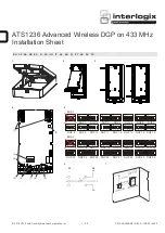


P/N 466-2938-
ML • REV A • ISS 29JAN19
3 / 50
address set with the DIP switches 1 to 4 on the DGP.
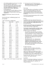
Figure 5 shows 15 possible wireless DGP addresses.
Note:
Do not use address 0.
LEDs
ATS1236 has the following LEDs:
•
D2: ATS bus Rx. Red, blinks when sending data to control
panel.
•
D4: ATS bus Tx. Green, blinks when receiving data from
control panel.
•
D6: LoNa communication. Green, blinks when valid packet
received from LoNa device.
•
D7: 63 bit communication. Blue, blinks when valid packet
received from 63 bit device.
•
D8: Radio sensitivity. Yellow, lit when the sensitivity is
reduced (−8 dBm) manually or automatically, for example,
in the programming menu when the panel is in set to an
EN compatible mode.
•
D9: Power supply. Green, lit when power is on.
•
D15: Heartbeat. Red, a triple blink every second indicates
module not enrolled, or a single blink every second
indicates module is enrolled.
Note:
LEDs are disabled when the housing is closed.
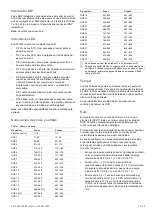
Zone and output numbering
Table 1: Zone numbering
Device
Zones
Outputs
Control panel
1
–16
1
–8
DGP 1
17
–48
17
–48
DGP 2
49
–80
49
–80
DGP 3
81
–112
81
–112
DGP 4
113
–144
113
–144
DGP 5
145
–176
145
–176
DGP 6
177
–208
177
–208
DGP 7
209
–240
209
–240
DGP 8
241
–272
241
–272
DGP 9
273
–304
273
–304
DGP 10
305
–336
305
–336
DGP 11
337
–368
337
–368
DGP 12
369
–400
369
–400
DGP 13
401
–432
401
–432
DGP 14
433
–464
433
–464
DGP 15
465
–480 [1]
465
–496
DGP 16 [2]
497
–528
497
–528
DGP 17
529
–560
529
–560
DGP 18
561
–592
561
–592
DGP 19
593
–624
593
–624
DGP 20
625
–656
625
–656
DGP 21
657
–688
657
–688
DGP 22
689
–720
689
–720
DGP 23
721
–752
721
–752
DGP 24
753
–784
753
–784
DGP 25
785
–816
785
–816
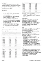
Device
Zones
Outputs
DGP 26
817
–848
817
–848
DGP 27
849
–880
849
–880
DGP 28
881
–912
881
–912
DGP 29
913
–944
913
–944
DGP 30
945
–976
945
–976
[1] Inputs 17 to 32 of Expander 15 cannot be used.
[2] You cannot connect more than 15 expanders to one system
databus. To connect more bus devices to a panel, it is necessary
to install ATS670 second RS485 LAN extension module.
Tamper
Two rubber push buttons provide front case and rear wall
tamper. To clear a DGP tamper condition, both tamper inputs
must be sealed. The enclosure should be firmly mounted on
a flat surface with the cover closed.
If either tamper input is open then a DGP tamper condition will
occur.
Relay
The receiver features one Single Pole Double Throw (SPDT)
Form C relay. This is the first output number of the DGP. Refer
to the control panel programming manual for details.
The relay is connected to output terminal J6 with Normally
Open and Normally Closed connections for your convenience.
The relay can be configured in 3 different modes to support
different applications. Use jumper J5 to select the mode
suitable for your requirements. See Figure 6.
•
No jumper (factory default): Dry contact closure provided
to output terminal. Maximum load is 30 VAC at 1A, or
30 VDC at 1 A.
•
Jumper between
− and C: Bus ground provided to output
terminal at typical 0V. Do not exceed relay rating, which is
maximum load 30 VAC at 1A, or 30 VDC at 1 A
•
Jumper between C and +: Bus voltage provided to output
terminal at typical 12 to 13 VDC. Maximum load at 12 V is
total panel current of 700 mA, this includes all connected
devices and expansion modules. Do not exceed relay
rating.
Programming
When connected to an Advisor advanced panel, configure the
DGP first. Use programming menu “2 Devices”.
Next, add and configure an appropriate wireless zone using
menu “4.1 Zones”. Also, add and configure wired zones if
connected.
See
Advisor Advanced Installation and Programming Manual
for more details.
Signal level
You can check the received signal level of each sensor using
“1 Service menu”. See
Advisor Advanced Installation and
Programming Manual
for more details.
To ensure the sensor is installed within an effective range of
the wireless expander or repeater, the installer can check the
Содержание Interlogix ATS1236
Страница 50: ...50 50 P N 466 2938 ML REV A ISS 29JAN19 ...


