


95-8401
6
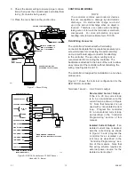
2.1
to 20 ma output corresponds to levels from 0 to full
scale. If a system fault is detected, the output drops
to less than 1.0 ma. The current output can be
calibrated in the field to ensure maximum accuracy.
(Refer to the “Calibration” section of this manual for
details.)
PROGRAMMING OPTIONS
(PREMIUM MODEL ONLY)
Each of the four relays is field selectable for either
normally open or normally closed contacts using
jumper plugs located on the printed circuit board
inside the controller. (See Table 3.)
The alarm relays are also switch programmable for
either normally energized or normally de-energized
operation (programmable as a group only, not
individually) . The fault relay is normally energized.
The low and auxiliary alarm relays are programmable
for either latching or non-latching operation. The
high alarm relay is always latching and the Fault
relay is non-latching. Latching relays are reset using
either the RESET pushbutton on the front panel of the
controller or an external reset switch.
The 4 to 20 ma circuit is selectable for isolated or
non-isolated operation.
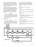
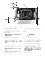
Automatic Diagnostics and Fault Identification
The microprocessor based controller features self-
testing circuitry that continuously checks for problems
that could prevent proper system response. When
power is applied, the microprocessor automatically
tests memory. In the Normal operating mode, it
continuously monitors the input signal from the
sensor/transmitter to ensure proper functioning. In
addition, a “watchdog” timer is maintained to ensure
that the program is running correctly. If a fault should
occur:
— The FAULT LED flashes.
— The digital display identifies the nature of the fault
using an alpha-numeric code. Refer to Table 4 for
an interpretation of the codes.
— The normally energized Fault output is de-ener-
gized.
— The dc current output drops to less than 1 ma.
NOTE
The fault code will be shown for about 2 seconds
out of every 5 seconds. The gas concentration at
the sensor will be displayed during the remaining
time. If more than one fault should occur, the
highest priority fault will be displayed. (Table 4 lists
the faults in order of priority.)
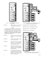
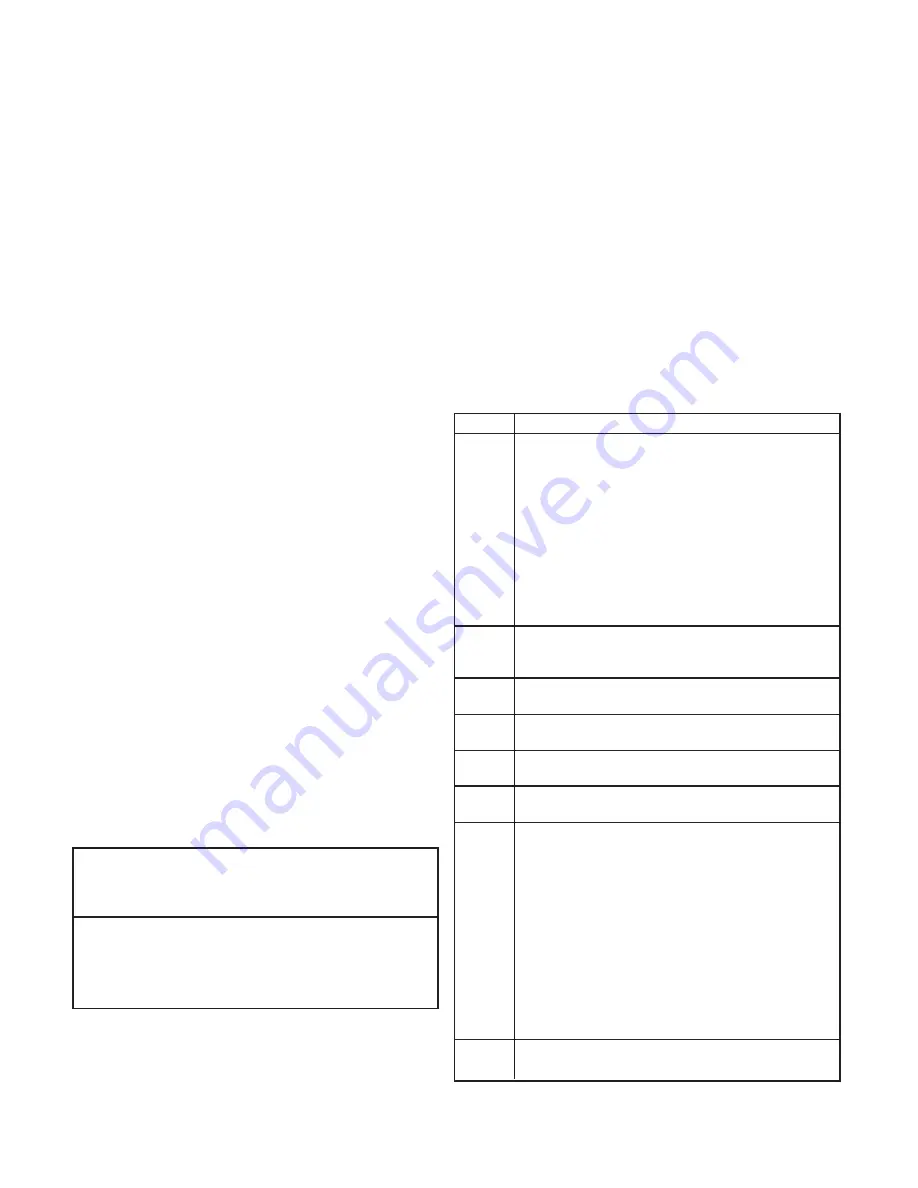
Table 3—Selectable Relay Options
Relay
Selectable
Selectable
Selectable
Normally
Normally
Latch/
Open/Closed
Energized/
Non-Latch
De-Energized
Low Y Y1
Y1
High Y Y1
N2
Auxiliary Y
Y1
Y1
Fault Y N3
N4
Y = Yes
N = No
1Selectable as a group, not individually 2Latching only
3Normally energized only
4No latching option
Table 4—System Status Codes
Status Condition
F9X
Initialization failure. (Subcodes are as follows.)
F91 EPROM
sumcheck
failure.
F92
System failure during startup - current too high or
too low.
F93 Watchdog
timer
failure.
F94 RAM
failure.
F95
Internal 5 volt power supply failure during startup.
F96
External 24 volt power supply failure during startup.
F97
Controller type invalid. Error in data from RAM.
F98
Watchdog timer reset the controller.
F70
External reset button has been activated for 15
seconds or longer. Self-clearing when button is
released.
F60
External 24 vdc power input is not in the 18 to 32
vdc range.
F50
Internal 5 volt power supply is not in the 4.75 to
5.25 volt range.
F40
Sensor fault (after startup). Input is above 35 ma
or below 2 ma.
F30
Negative zero drift. Sensor input is –9% full scale
or lower.
F2X
Calibration error. (Subcodes are as follows.)
F20
General calibration fault, or calibration aborted due
to a higher priority fault.
F21
Time ran out while waiting for the user to apply gas
to the sensor.
F22
Sensor input is too low. The sensor cannot
generate enough offset to get an accurate
calibration. Replace sensor.
F23
Sensor is too sensitive for the controller to read
100% full scale. Replace sensor.
F24
Zero gas level too high, or sensor zero input over
limit.
F10
Sensor reaching end of life. Consider replacing the
sensor within the next two calibration periods.


