UTC Fire and Security Det-Tronics R8471B Скачать руководство пользователя страница 20

95-8401

18

2.1

the auxiliary alarm setpoint.  Press the appropriate 
button to obtain the desired reading on the digital 
display.

5.  When no changes have been made for 5 sec-

onds, the Auxiliary LED goes out, the CAL LED 
blinks, and the digital display indicates the cali-
bration gas concentration.  Press the appropriate 
button to change the calibration gas concentra-
tion as required.

6.  When no changes have been made for 5 sec-

onds, the controller automatically returns to the 
Normal operating mode.

7.  Record the new values for future reference.

NOTE

The alarm setpoints, calibration gas concentration, 
and calibration data are stored in non-volatile 
memory and are retained in the event of a power 
loss.  However, if power is interrupted while 
performing the Setpoint Adjustment or Calibration 
procedure, the entire procedure must be repeated 
when power is restored.

CALIBRATION

Various factors affect the time interval between 
periodic recalibrations.  Exposure to certain 
contaminants in the air, accumulation of contaminants 
on the filter, or an extended period of normal 
operation can cause changes in sensitivity.  Since 
each application is different, the length of time 
between regularly scheduled recalibrations can 
vary from one installation to the next. In general, the 
more frequently a system is checked, the greater the 
reliability.  Calibration 

must 

be performed:

— When a new system is initially put into service

— When the sensing element is replaced

— If a transmitter or controller used in conjunction with 

the sensor is replaced

— When the hydrophobic filter is cleaned or replaced.

The following calibration schedule is recommended 
when placing a new sensor into operation and will 
ensure reliable operation in most applications:

1.  One hour after power-up

2. One 

week 

later

3.  Every 30 days thereafter, or as determined by the 

needs of the specific application.

IMPORTANT

To ensure adequate protection, the H

2

S detection 

system must be calibrated on a regularly 
scheduled basis
.  

Loss of sensitivity can be caused by various fac-
tors.  One common cause is by clogging of the 
hydrophobic filter by dirt, oil, paint, etc.  Problems 
of this nature will not be detected by the system’s 
diagnostic circuitry.  While performing detec-
tor calibration, the operator should examine the 
hydrophobic filter of the sensor.  If it cannot be 
properly cleaned, it should be replaced.

The detector must be calibrated using hydrogen 
sulfide mixed with either air or nitrogen.  For best 
results, a calibration gas concentration equal 
to the high alarm setpoint or 50% of full scale is 
recommended.

NOTE

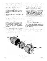
If the sensing element is being replaced, refer to 
the “Sensing Element Replacement” section (under 
“Maintenance”) in this manual for information 
regarding replacement and calibration of the 
sensor.

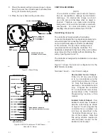
CALIBRATION PROCEDURE

The H

2

S detection system can be calibrated using 

either of two methods:

1.

  Transmitter calibration (if a transmitter is 

used)

 This method of calibration can be per-

formed by one person.  All adjustments are made 
at the transmitter.  Calibration of certain transmit-
ter models requires removing the enclosure cover, 
therefore, the hazardous area must be de-classi-
fi ed.


When transmitter calibration is performed, an 
initial calibration of the controller must be per-
formed in addition to the transmitter calibration.  
This calibration of the controller is not the same 
as “2.  Controller Calibration” described below.  
It involves setting factory default calibration val-
ues in the controller that will ensure accuracy 
when used in conjunction with a properly cali-
brated transmitter.  Since these default values do 
not change, the procedure does not need to be 
repeated with subsequent transmitter recalibra-
tions.  This controller calibration is accomplished 
by momentarily entering the Sensor Replacement 
mode.  Upon entering the Sensor Replacement 
mode, the controller automatically sets the fac-
tory default controller calibration values.  (Follow 
the procedure described in the “Setting Controller 
Default Values” section.)

Содержание Det-Tronics R8471B

Страница 1: ...Instructions 95 8401 H2S Controller R8471B 2 1 8 07 95 8401 ...

Страница 2: ...TALLATION CHECKLIST 16 Section III System Startup STARTUP PROCEDURE 16 SETPOINT ADJUSTMENT 17 Setpoint Display Mode 17 Setpoint Adjustment Procedure 17 CALIBRATION 18 Calibration Procedure 18 Current Output Calibration 20 Section IV System Maintenance ROUTINE MAINTENANCE 20 Manual Check of Output Devices 20 Checkout in Normal Mode 20 Hydrophobic Filter 20 Sensing Element Replacement 21 TROUBLESHOO...

Страница 3: ... controller is easily field pro grammable Base model is furnished with solid state alarm and fault outputs Premium model is furnished with relay outputs and a 4 to 20 ma dc output Current output is selectable for isolated non isolated operation Rack compatible with Det Tronics R7400 series flame controllers Variety of racks available in 4U or 3U height configu ration APPLICATION INFORMATION Hydrog...

Страница 4: ... volts dc maximum RELAY CONTACTS Premium model only Selectable normally open normally closed contacts rated 5 amperes at 30 vdc 250 vac CURRENT OUTPUT Premium model only 4 to 20 milliamperes dc current with a maximum external loop resistance of 600 ohms at 20 to 32 vdc DIMENSIONS See Figure 1 SHIPPING WEIGHT approximate 2 0 pounds 0 9 kilogram SYSTEM APPROVAL The R8471B Controller base and premium...

Страница 5: ...sically safe is CSA certified and FM approved for Class I Division 1 Groups A B C and D DIMENSIONS See Figure 2 for dimensions of the C7064E Sensor and Figure 3 for dimensions of the junction box SHIPPING WEIGHT Approximate 2 5 pounds 1 1 kilograms SYSTEM OPERATION SENSOR The C7064C intrinsically safe and C7064E explosion proof H2S Sensors use an electrochemical sensing element to detect the prese...

Страница 6: ...r special transmitter features such as relay contacts or visible annunciators a variety of Det Tronics transmitters are available for use with either electrochemical or solid state H2S sensors Refer to the Ordering Information section of this manual for more information CONTROLLER Faceplate Description The controller faceplate provides LEDs for identifying status conditions a digital display and b...

Страница 7: ...hecked by pressing the RESET pushbutton located on the front panel of the controller See Setpoint Adjustment and Calibration sections of this manual for additional information Outputs The R8471B Controller is available in a Base version and a Premium version The differences between the two models are the output configuration and programming options BASE MODEL The base controller is furnished with ...

Страница 8: ...current output drops to less than 1 ma NOTE The fault code will be shown for about 2 seconds out of every 5 seconds The gas concentration at the sensor will be displayed during the remaining time If more than one fault should occur the highest priority fault will be displayed Table 4 lists the faults in order of priority Table 3 Selectable Relay Options Relay Selectable Selectable Selectable Norma...

Страница 9: ...tep by step programming and calibration procedures refer to the corresponding sections in this manual The controller can operate in any of the following modes Operating modes other than Normal are selected by pressing the appropriate pushbutton s located on the controller front panel See Figure 5 NORMAL In the Normal operating mode with no alarm condition Digital display is on and indicates the se...

Страница 10: ...SPLAY MODE If the RESET button is held for approximately one second the controller enters the Setpoint Display mode In this mode the digital display sequentially shows the programmed alarm setpoints and calibration gas concentration Each value is displayed for approximately 2 seconds After completing the sequence the controller automatically returns to the Normal operating mode if the RESET button...

Страница 11: ...shes Finally the current output level during calibration is generated while the CAL LED flashes The microprocessor automatically returns to the normal operating mode at the end of the sequence Adjustments to the current output level are made by pressing the RESET increase or SET decrease button This procedure requires a dc current meter to monitor the actual controller dc milliampere output Sectio...

Страница 12: ...should never be poured in temperatures that are below freezing since the water in the sealing compound will freeze and the compound will not dry properly Contamination problems can then result when temperatures rise above the freezing point and the compound thaws The shielding of the cable should be stripped back to permit the seal to form around the individual leads rather than around the outside...

Страница 13: ... installation however do not over tighten NOTE Coat the sensor threads with an appropriate grease to ease installation and also lubricate the junction box cover threads to ensure a water tight enclosure The recommended lubricant is a silicone free polyalphaolefin grease part number 005003 001 available from Detector Electronics 8 Connect the sensor wires to the terminal block marked to sensor See ...

Страница 14: ... R8471B H2S Controller Terminals 1 and 2 4 to 20 ma dc output Non Isolated Current Output If the 4 to 20 ma current loop is to be non isolated wire the current loop as shown in Figure 12 Note that terminal 2 is not used with a non isolated current loop Program the controller for a non isolated current loop as described in the Controller Programming section of this manual Isolated Current Output If...

Страница 15: ...IN THE TOP BRACKET IN LINE WITH THE CLIP IN THE BOTTOM BRACKET 3 GAS CONTROLLERS ARE APPROX ONE INCH WIDE AND REQUIRE ONE RAIL FOR INSERTION PLACE CLIPS IN LINE WITH GUIDE RAILS CAGES WILL ACCEPT AS MANY GAS CONTROLLERS AS RAILS PROVIDED CONTROLLER POSITIONS FOR HT DIM A DIM B DIM C DIM D DIM E FIRE GAS INCH MM INCH MM INCH MM INCH MM INCH MM 8 16 4U 19 00 482 6 18 30 464 8 17 36 440 9 4 00 101 6 ...

Страница 16: ...Low Alarm Output Terminals 15 and 16 Fault Output Figure 12 A Typical System R8471B with Relay Outputs Non Isolated Current Output and C7064E Sensor CURRENT OUTPUT CHASSIS GROUND POWER SENSOR EXTERNAL RESET HIGH ALARM HIGH ALARM OC AUX ALARM AUX ALARM OC LOW ALARM LOW ALARM OC FAULT FAULT OC 1 3 4 5 6 7 8 9 10 11 12 13 14 15 16 18 TO 32 VDC POWER SIGNAL 2 OC OPEN COLLECTOR OUTPUT BASE MODEL ONLY B...

Страница 17: ...lly Open or Normally Closed refers to the condition of the relay contacts when Normally de energized operation is selected Refer to the setting of SW1 2 below If the relays are Normally Energized the condition of the relay contacts will be reversed Latching Non Latching Relays The Low and Auxiliary alarm relays are programmable for latching or non latching operation The High alarm relay is always ...

Страница 18: ...ack 10 Proper ventilation is provided to prevent over heating of the controller Proceed to System Startup Setpoint Adjustment and Calibration Section III System Startup STARTUP PROCEDURE 1 Output loads that are normally actuated by the system should be secured remove power from all output devices to prevent undesired activation 2 Check all external wiring for proper connection Be sure that the sen...

Страница 19: ... mode without affecting the calibration settings 2 At the end of the two second interval the Low LED goes out the High LED begins to blink and the digital display shows the high alarm setpoint 3 Two seconds later the High LED goes out and the Auxiliary LED blinks The digital display now shows the programmed auxiliary alarm setpoint 4 Two seconds later the Auxiliary LED goes out and the CAL LED bli...

Страница 20: ...tion the H2S detection system must be calibrated on a regularly scheduled basis Loss of sensitivity can be caused by various fac tors One common cause is by clogging of the hydrophobic filter by dirt oil paint etc Problems of this nature will not be detected by the system s diagnostic circuitry While performing detec tor calibration the operator should examine the hydrophobic filter of the sensor ...

Страница 21: ...The FAULT LED comes on and the digital display stops flashing The con troller is now set for the factory default values 3 To exit the Sensor Replacement mode press the RESET button The controller returns to the nor mal operating mode after a time delay The above procedure does not need to be performed with each recalibration unless a controller calibration described below is performed For informat...

Страница 22: ...button to obtain the desired current output level for the calibrate mode The default level is 4 0 ma 6 When no changes have been made for 7 sec onds the system automatically returns to the Normal operating mode and saves the data in non volatile memory 7 Remove the meter from the system output and reconnect the outputs for normal operating condi tions Section IV System Maintenance ROUTINE MAINTENA...

Страница 23: ...y return to the Normal mode when power is restored after a time delay To prevent the possibility of alarms allow the system to warm up in the sensor replacement mode The sensor replacement mode can be entered during the power up time delay by holding the RESET button for 7 seconds If performing a transmitter calibration leaving the controller in the Sensor Replacement mode until after the calibrat...

Страница 24: ...failure FAULT LED on 1 Power up time delay up to 5 minutes digital display blank 2 If condition continues after 5 minutes repeat power up If problem continues replace controller F91 to F98 Status 1 Initialization failure Repeat power up If successful re program and re calibrate If not replace controller F92 Status 1 Sensor failure during startup Current is over 35 ma or below 2 ma F94 Status 1 RAM...

Страница 25: ...re used with gas controllers only 4U racks can house gas or flame controllers in any combina tion See Figures 9 and 10 Rack sizes are available to handle up to 8 flame controllers or up to 16 gas controllers SENSOR C7064C Sensor Housing C7064E Sensor Housing Electrochemical Sensing Element Sensor Junction Box ACCESSORIES Silicone Free Grease Open Frame Power Supply 3 6 amperes at 24 vdc Open Frame...

Страница 26: ...95 8401 24 2 1 Recommended Test Form Detector Detector Date Date Date Number Location Installed Checked Calibrated Remarks ...

Страница 27: ...95 8401 25 2 1 Fault Record Sheet Date Time Detector System Status Operator Comments Affected ...

Страница 28: ...95 8401 26 2 1 ...

Страница 29: ... IR Combustible Gas Detector Eagle Quantum Premier Safety System Eagle Logic Solver Safety System Det Tronics the DET TRONICS logo Eagle Quantum Premier and Eclipse are registered trademarks or trademarks of Detector Electronics Corporation in the United States other countries or both Other company product or service names may be trademarks or service marks of others Copyright Detector Electronics...

Отзывы: