Chapter 10 – Emergency Operation
SB47JRT – 0075522
51
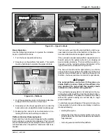
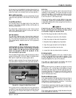
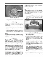
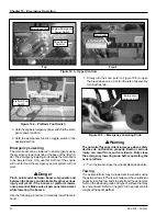
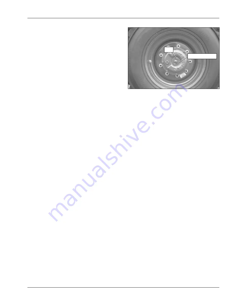
Figure 10.6 – Drive Wheel
8. Pull the steering float valve knob out. The knob is
located behind the rear door on the right side of the
turntable next to the fuel tank.
9. Do not exceed 16 km/h (10 mph) when towing. Use
caution when traveling around a curve or when turn-
ing a corner. If the tow bar contacts the chassis the
steering mechanism might be damaged or the tow
vehicle and the aerial platform could jackknife.
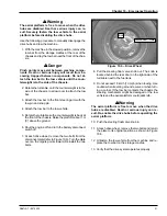
A
Warning
The aerial platform is free to move when the drive
hubs are disabled. Death or serious injury can re-
sult. Re-enable the drive hubs before operating the
aerial platform.
10. Push the steering float valve knob in.
11. At each drive wheel, remove the two bolts and return
the plate to its original position as shown in Figure
10.6.
12. Unfasten the tow vehicle from the machine and re-
place the tow bar on the storage cradles.
13. Verify that the drive system operates properly.
A
Warning
The aerial platform is free to move when the drive
hubs are disabled. Death or serious injury can re-
sult. Securely fasten the tow vehicle to the aerial
platform before disabling the drive hubs.
Use the following procedure to manually disengage the
drive hubs and tow the machine.
1. With the machine in the stowed position, remove the
tow bar from the storage cradles at the rear of the
chassis and lay the tow bar near the front of the chas-
sis.
A
Danger
Pinch points may exist between machine compo-
nents. Death or serious injury will result from be-
coming trapped between components. Do not at-
tach the tow bar to the tow vehicle until the coun-
terweight is to the side of the chassis.
2. Rotate the turntable, until the counterweight is to the
side of the chassis, to allow room to attach the tow
bar.
3. Attach the tow bar to the front steering arm with the
tow pin and snap pin.
4. Attach the tow bar to the tow vehicle.
5. Rotate the turntable so the counterweight is back at
the front of the chassis. Raise the platform about 1 m
(3
′
) above the ground.
6. Shut the engine off and turn the battery disconnect
switch off.
7. At each drive wheel, remove the two bolts from the
disconnect plate (refer to Figure 10.6). Turn the plate
over so the nipple points inward. Reinstall the two
bolts.
Bolt
Disconnect Plate
Содержание SB47JRT
Страница 1: ...SB47JRT Operator Manual Jan 08 PN 508361 000 SB47JRT ...
Страница 2: ......
Страница 6: ......
Страница 13: ...Chapter 2 Specifications SB47JRT 0075522 7 Engine Oil Viscosity Cummins B3 3 Deutz F3L 2011F ...
Страница 14: ...Chapter 2 Specifications 8 SB47JRT 0075522 ...
Страница 30: ...Chapter 6 Controls 24 SB47JRT 0075522 ...
Страница 44: ...Chapter 7 Prestart Inspection 38 SB47JRT 0075522 ...
Страница 50: ...Chapter 8 Operation 44 SB47JRT 0075522 Figure 8 6 Platform Work Lights ...
Страница 58: ...Chapter 10 Emergency Operation 52 SB47JRT 0075522 ...
Страница 64: ...Chapter 11 Troubleshooting 58 SB47JRT 0075522 ...
Страница 66: ...Appendix A Glossary SB47JRT 0075522 ...
Страница 67: ......

