


© UPLIFT Desk
• 800-349-3839 • [email protected] • upliftdesk.com
5
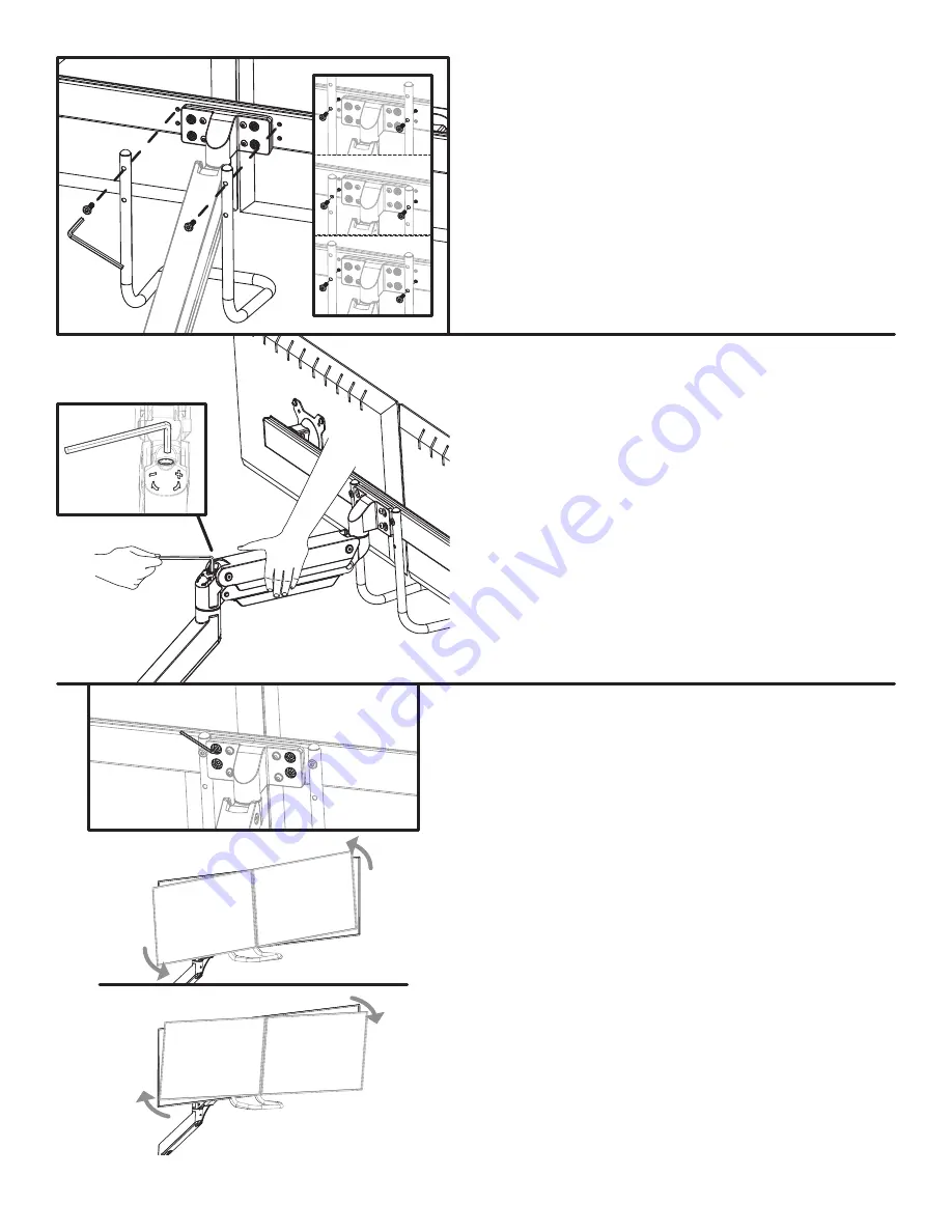
Step 10
The angle of the Bar can be adjusted up to 4 degrees
in either direction.
To adjust the angle of the Bar, use the 4mm Allen
wrench to
slightly loosen
the four screws shown on
the back of the Bar attachment piece.
Do not remove
these screws completely.
Once the four screws are loose, adjust the angle of the
Bar and monitors until they are positioned how you
like them and then re-tighten the four screws.
Step 8
There are four options for the attachment of the Han-
dle to the Bar. Choose between the two sets of holes
on the Handle and two sets of holes in the Bar to de-
termine which combination is best for you and allows
the bottom of the Handle to clear the bottom of your
monitors.
Note:
When installing the Handle, you may need to
squeeze the ends together or pull them apart slightly
in order to align the holes in the Handle with the holes
in the Bar.
Connect the Handle to the Bar using the two M6x22
screws and the 4mm Allen wrench.
Step 9 - Counterbalance
Move the monitor assembly to any position and re-
lease it. If the monitor assembly does not drift up or
down, the arm is properly counterbalanced.
If the monitor assembly does not remain where you
positioned it, you will need to adjust the tension of
the gas spring to properly support the weight of your
monitor assembly.
If the monitor assembly drifted down, hold the Upper
Arm in a horizontal position and use the 6mm Allen
Wrench to turn the adjustment screw toward the “+”
until the monitor assembly remains in place when you
let go.
If the monitor assembly drifted upward, turn the ad-
justment screw towards the “-” symbol.


