


Vision™ OPLC™ V1040-T20B
Installation Guide
8
Unitronics
Communication Ports
This series comprises a USB port, 2 RS232/RS485 serial ports and a CANbus port. An additional
port may be ordered separately and installed. This port may be either Ethernet, or serial (COM 3).
For the most updated information regarding ports and their installation, please refer to the Technical
Library at www.unitronics.com.
▪
Turn off power before making communications connections.
Caution
▪
Always use the appropriate port adapters.
The USB port may be used for programming, OS download, and PC access.
Note that
COM port 1 function is suspended when this port is physically connected to a PC
.
The serial ports are type RJ-11 and may be set to either RS232 or RS485 via DIP switches, in
accordance with the table shown below.
Use RS232 to download programs from a PC, and to communicate with serial devices and
applications, such as SCADA.
Use RS485 to create a multi-drop network containing up to 32 devices.
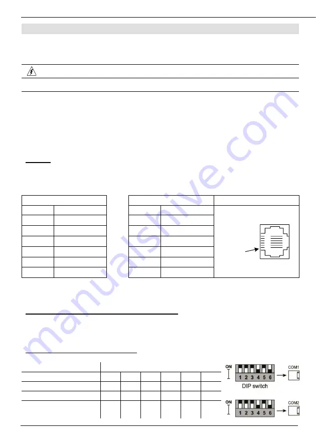
Pinouts
The pinouts below show PLC port signals.
To connect a PC to a port that is set to RS485, remove the RS485 connector, and connect the PC to
the PLC via the programming cable. Note that this is possible only if flow control signals are not used
(which is the standard case).
RS232
RS485**
Controller Port
Pin #
Description
Pin #
Description
Pin #1
1*
DTR signal
1
A signal (+)
2
0V reference
2
(RS232 signal)
3
TXD signal
3
(RS232 signal)
4
RXD signal
4
(RS232 signal)
5
0V reference
5
(RS232 signal)
6*
DSR signal
6
B signal (-)
*Standard programming cables do not provide connection points for pins 1 and 6.
**When a port is adapted to RS485, Pin 1 (DTR) is used for signal A,
and Pin 6 (DSR) signal is used for signal B.
RS232 to RS485: Changing DIP Switch Settings
The ports are set to RS232 by factory default.
To change the settings, first remove the Snap-in I/O Module, if one is installed, and then set the
switches according to the following table.
RS232/RS485: DIP Switch Settings
The settings below are for each COM port.
Switch Settings
1
2
3
4
5
6
RS232*
ON
ON
ON
OFF
ON
OFF
RS485
OFF
OFF
OFF
ON
OFF
ON
RS485 with
termination**
ON
ON
OFF
ON
OFF
ON


