background image

UIS-WCB1 Installation Guide 


Unitronics 


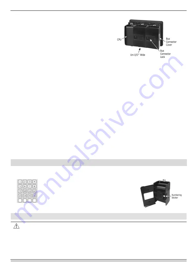
5.  Slide the Bus Connector Lock all the way to 

the left as shown in the accompanying figure. 

6.  If there is already a module located to its 

right, complete the connection by sliding the 

Bus Connector lock of the adjacent unit to the 
left. 

7.  If the module is the last in the configuration, 

leave the I/O bus connector covered. 


Removing a Module 

1.  Turn off the system power. 
2.  Disconnect the I/O terminals (#2,3,7,8 in the diagram). 
3.  Disconnect the Uni-I/O™ module from the adjacent units: slide its Bus Connector Lock 

to the right. If there is a unit located on its right, slide the lock of this module to the 

right as well. 

4.  On the Uni-I/O™ module, pull the top DIN-rail clip up and the bottom clip down. 
5.  Open the door of the Uni-I/O™ module and hold it with two fingers as shown in the 

figure on page 3; then pull it carefully from its place.


Installing Uni-I/O™ modules onto a DIN-rail  

To mount modules onto a DIN-rail, follow steps 1-7 in Installing a Uni-I/O™ Module onto a 

UniStream™ HMI Panel on page 3. 
In order to connect the modules to a UniStream™ controller, you must use a Local 

Expansion Kit.  
These kits are available with and without power supplies, and with cables of varying 

lengths. For complete information, please refer to the installation guide of the relevant 

Local Expansion Kit. 


Numbering Modules  

You can number modules for reference purposes. A set of 20 stickers is provided with 

every CPU-for-Panel; use these stickers to number the modules.  


The set contains numbered and blank 

stickers as shown in the figure to the left.  


Place them on the modules as shown in the 
figure to the right. 


Wiring 


This equipment is designed to operate only at SELV/PELV/Class 2/Limited Power 

environments. 


All power supplies in the system must include double insulation. Power supply 
outputs must be rated as SELV/PELV/Class 2/Limited Power. 


Do not connect either the ‘Neutral’ or ‘Line’ signal of the 110/220VAC to device’s 0V 
point. 


Do not touch live wires. 


Содержание Uni-I/O UIS-WCB1

Страница 1: ...ation for UIS WCB1 Uni I O module Technical specifications may be downloaded from the Unitronics website The UniStream platform comprises CPU controllers HMI panels and local I O modules that snap together to form an all in one Programmable Logic Controller PLC Install Uni I O modules Onto the back of any UniStream HMI Panel comprising a CPU for Panel Onto a DIN rail using a Local Expansion Kit Th...

Страница 2: ...dance with the standards and limitations given in the product s technical specification sheet Do not place in water or let water leak onto the unit Do not allow debris to fall inside the unit during installation Install at maximum distance from high voltage cables and power equipment Kit Contents 1 Uni I O module 4 I O terminal blocks 2 black and 2 gray Uni I O Diagram 1 DIN rail clips Provide phy...

Страница 3: ...O module or to the Base Unit of the Local Expansion Kit Caution If the I O module is located last in the configuration and nothing is to be connected to it do not remove its Bus Connector Cover Installation Turn off system power before connecting or disconnecting any modules or devices Use proper precautions to prevent Electro Static Discharge ESD Installing a Uni I O Module onto a UniStream HMI P...

Страница 4: ...i I O modules onto a DIN rail To mount modules onto a DIN rail follow steps 1 7 in Installing a Uni I O Module onto a UniStream HMI Panel on page 3 In order to connect the modules to a UniStream controller you must use a Local Expansion Kit These kits are available with and without power supplies and with cables of varying lengths For complete information please refer to the installation guide of ...

Страница 5: ...ce from high voltage cables and power equipment Wiring Procedure Use crimp terminals for wiring use 26 12 AWG wire 0 13 mm2 3 31 mm2 1 Strip the wire to a length of 7 0 5mm 0 250 0 300 inches 2 Unscrew the terminal to its widest position before inserting a wire 3 Insert the wire completely into the terminal to ensure a proper connection 4 Tighten enough to keep the wire from pulling free UIS WCB1 ...

Страница 6: ...rth of the system Earthing the cables shield Connect the cable shield to the earth of the system preferably to the metal cabinet chassis Note that the shield must be connected only at one end of the cable typically earthing the shield at the UIS WCB1 end performs better Keep shield connections as short as possible Ensure shield continuity when extending shielded cables NOTE For detailed informatio...

Страница 7: ...nected Note that in this configuration the direction pin cannot be used as normal input Input wiring sink Input wiring source High Speed Input wiring sink High Speed Input wiring source Wiring the Analog Inputs Both inputs share the common point CM0 NOTE Each input offers two modes voltage or current You can set each input independently The mode is determined both by wiring and by the hardware con...

Страница 8: ...UIS WCB1 Installation Guide 8 Unitronics Voltage Differential Single ended Current 2 wire 3 wire 4 wire ...

Страница 9: ...temperature inputs isolation may be bypassed when using an exposed junction non isolated thermocouple in conjunction with analog inputs or another exposed junction thermocouple which can lead to flow of unwanted currents through the thermocouple wires that might interfere with thermocouple voltage reading In order to maintain temperature inputs isolation when using one or more of the analog inputs...

Страница 10: ...current limiting device in series with the relay contacts All 8 relay outputs share the common point CM5 Increasing contact life span To increase the life span of the relay contacts and protect the module from potential damage by reverse EMF connect a clamping diode in parallel with each inductive DC load an RC snubber circuit in parallel with each inductive AC load DC Load AC Load ...

Страница 11: ...mage the module Normal Transistor Output High Speed PWM Output Wiring the Analog Outputs NOTE The outputs are not isolated Each output offers two modes voltage or current You can set each output independently The mode is determined both by wiring and by the hardware configuration within the software application Voltage and current modes use distinct points Connect only the point associated with th...

Страница 12: ...uding but not limited to any impliedwarranties of merchantability fitness for aparticular purpose or non infringement Unitronicsassumes no responsibility for errors or omissions in the information presented in this document In no event shallUnitronics be liable for any special incidental indirect orconsequential damages of anykind oranydamages whatsoever arising outof or in connection with theuse ...

Отзывы: