


Commissioning
Classic P3 60-150 A
01/2018 - V1
20
Co
m
m
iss
io
ni
ng
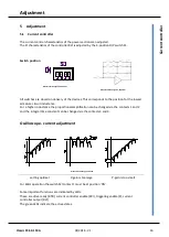
Current controller
(Switch S1 on the power section)
The current amplification is adjusted to a low armature circuit inductance (all switches ”On”)
High inductance values can lead to motor oscillation which cannot be influenced by means of the
speed controller. In this case, first set switch S1-2 to ”Off”. If the drive still does not run smoothly,
set the switch S1-1 to ”Off”.
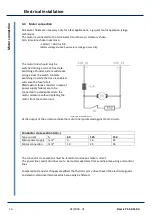
The current controller response can be measured by means of an oscilloscope across the test
point X4:20 (see chapter 5.0).
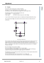
Speed controller amplification
Adjust on the REG board.
Adjust the P-term to the lowest possible setting from 1 to 5 (switch S4).
Adjust the I-term according to the centrifugal mass (switch S5):
large centrifugal mass - high adjusted value
small centrifugal mass - low adjusted value
With the command value set to 10% speed, increase the amplification by turning the
potentiometer Xp clockwise. When the drive begins to oscillate, reduce the amplification by
turning the potentiometer anti-clockwise by approximately 10%.
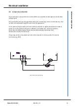
For the fine adjustment of the amplification the control response should be measured by means
of an oscilloscope across the test point X4:15
Further adjustments
such as speed, peak current, continuous current, etc. (rf. to the manual REG)
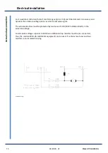
Switching off
If the switch 'drive enable' is opened, or the drive enable voltage is switched to 0V, LED L1 and L2
will extinguish and the drive decelerates.
After approx. 2s the thyristor triggering circuit is disabled
Commissioning adjustments
The adjustments should be documented in the protocol and the adjustment potentiometers
should be sealed with a suitable lacquer.


