


32
Humidi-MiZer
®
System Control Connections
HUMIDI-MIZER — SPACE RH CONTROLLER
NOTE: The Humidi-MiZer system is a factory installed
option.
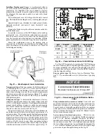
The Humidi-MiZer dehumidification system requires a
field-supplied and installed space relative humidity control de-
vice. This device may be a separate humidistat control (contact
closes on rise in space RH above control setpoint) or a combi-
nation thermostat-humidistat control device such as Carrier’s
Edge
®
Pro Thermidistat with isolated contact set for dehumidi-
fication control. The humidistat is normally used in applica-
tions where a temperature control is already provided (units
with PermierLink™ control).
50TC 08-14 UNIT SIZES
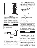
To connect the Carrier humidistat (HL38MG029):
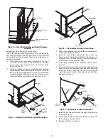
1. Route the humidistat 2-conductor cable (field-supplied)
through the hole provided in the unit corner post.
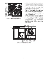
2. Feed wires through the raceway built into the corner post
(see Fig. 36) to the 24-v barrier located on the left side of
the control box. The raceway provides the UL-required
clearance between high-voltage and low-voltage wiring.
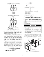
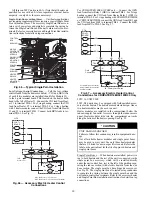
3. Use wire nuts to connect humidistat cable to two PINK
leads in the low–voltage wiring as shown in Fig. 62.
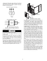
To connect the Thermidistat device (33CS2PPRH-01):
1. Route the Thermidistat multi-conductor thermostat cable
(field-supplied) through the hole provided in the unit cor-
ner post.
2. Feed wires through the raceway built into the corner post
(see Fig. 36) to the 24-v barrier located on the left side of
the control box. The raceway provides the UL-required
clearance between high-voltage and low-voltage wiring.
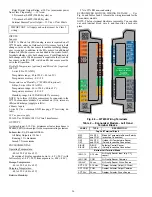
3. The Thermidistat has dry contacts at terminals D1 and D2
for dehumidification operation (see Fig. 64). The dry con-
tacts must be wired between CTB terminal R and the
PINK lead to the LTLO switch with field-supplied wire
nuts. Refer to the installation instructions included with
the Carrier Edge Pro Thermidistat device for more infor-
mation.
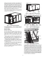
50TC 16 UNIT SIZE
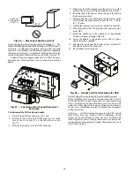
To connect the Carrier humidistat (HL38MG029):
1. Route the humidistat 2-conductor cable (field-sup-
plied) through the bushing the unit’s louvered end
panel (see Fig. 51).
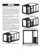
2. Route the cable through the snap-in wire tie and up to the
web bushing near the control box.
3. Feed the cable through the bushing and into the bottom
left side of the control box after removing one of the two
knockouts in the corner of the box. Use a connector to
protect the cable as it enters the control box.
4. Use the connector and the wire tie to reduce any slack in
the humidistat cable to ensure that it will not be damaged
by contact with the condenser coil (see Fig. 51).
5. Use wire nuts to connect humidistat cable to two PINK
leads in the low–voltage wiring as shown in Fig. 63.
To connect the Thermidistat device (33CS2PPRH-01):
1. Route the Thermidistat multi-conductor thermostat
cable (field-supplied) through the bushing the unit’s
louvered end panel (see Fig. 51).
2. Route the cable through the snap-in wire tie and up to the
web bushing near the control box.
3. Feed the cable through the bushing and into the bottom
left side of the control box after removing one of the two
knockouts in the corner of the box. Use a connector to
protect the cable as it enters the control box.
4. Use the connector and the wire tie to reduce any slack in
the thermostat cable to ensure that it will not be damaged
by contact with the condenser coil (see Fig. 51).
5. The Thermidistat has dry contacts at terminals D1 and D2
for dehumidification operation (see Fig. 64). The dry con-
tacts must be wired between CTB terminal R and the
PINK lead to the LTLO switch with field-supplied wire
nuts. Refer to the installation instructions included with
the Carrier Edge Thermidistat device literature for more
information.
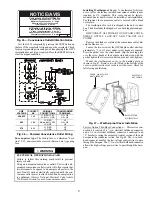
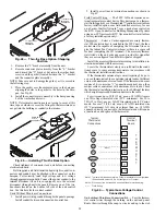
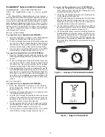
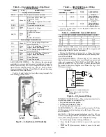
Fig. 60 — Accessory Field-Installed Humidistat
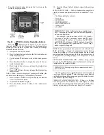
Fig. 61 — Edge Pro Thermidistat
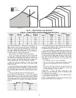
% RELATIVE HUMIDITY
®
Содержание Carrier WeatherMaker 50TC A08 Series
Страница 4: ...4 Fig 2 Unit Dimensional Drawing Size 08 09 12 Units...
Страница 5: ...5 Fig 2 Unit Dimensional Drawing Size 08 09 12 Units cont...
Страница 6: ...6 Fig 3 Unit Dimensional Drawing Size 14 Unit...
Страница 7: ...7 Fig 3 Unit Dimensional Drawing Size 14 Unit cont...
Страница 9: ...9 Fig 4 Unit Dimensional Drawing Size 16 Unit cont...
Страница 13: ...13 Fig 8 Roof Curb Details Size 16 Unit...
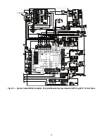
Страница 33: ...33 Fig 62 Typical Humidi MiZer Adaptive Dehumidification System Humidistat Wiring 50TC 08 14 Unit Sizes...
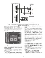
Страница 34: ...34 Fig 63 Typical Humidi MiZer Adaptive Dehumidification System Humidistat Wiring 50TC 16 Unit Sizes HUMIDISTAT...
Страница 50: ...50 Fig 73 50TC 16 Control Box Component PremierLink Locations...
Страница 51: ...51 Fig 74 Typical PremierLink Control Wiring Diagram...
Страница 52: ...52 Fig 75 Typical PremierLink Control Wiring Diagram with Humidi MiZer System Option...
Страница 64: ...64 Fig 106 Typical RTU Open Controller Wiring Diagram 50TC 08 14 Size Units...
Страница 65: ...65 Fig 107 Typical RTU Open Controller Wiring Diagram 50TC 16 Size Unit...
Страница 66: ...66 Fig 108 Typical RTU Open Controller Wiring Diagram with Humidi MiZer System Option 50TC 08 14 Size Units...
Страница 67: ...67 Fig 109 Typical RTU Open Controller Wiring Diagram with Humidi MiZer System Option 50TC 16 Size Units...