


29
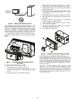
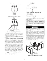
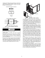
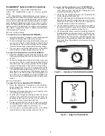
bushing near the control box. Route the wire through the bush-
ing and into the bottom left side of the control box after remov-
ing one of the two knockouts in the corner of the box. Using a
connector at the control box to protect the wire as it passes into
the control box. Pull the wires over to the terminal strip at the
upper left corner of the Central Terminal Board (CTB). Use the
connector at the control box and the wire tie to take up any
slack in the thermostat wire to ensure that it will not be dam-
aged by contact with the condenser coil. See Fig. 51.
NOTE: If thru-the-bottom connections accessory is used, refer
to the accessory installation instructions for information on
routing power and control wiring.
Fig. 51 — Thermostat Wire Routing
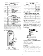
Heat Anticipator Settings — Set heat anticipator settings at
0.14 amp for the first stage and 0.14 amp for second-stage heat-
ing, when available.
Electric Heaters
50TC 08-14 UNIT SIZES
50TC*08-14 units may be equipped with field-installed acces-
sory electric heaters. The heaters are modular in design, with
heater frames holding open coil resistance wires strung
through ceramic insulators, line-break limit switches and a
control contactor. One or two heater modules may be used in a
unit.
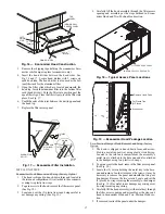
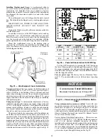
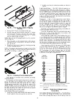
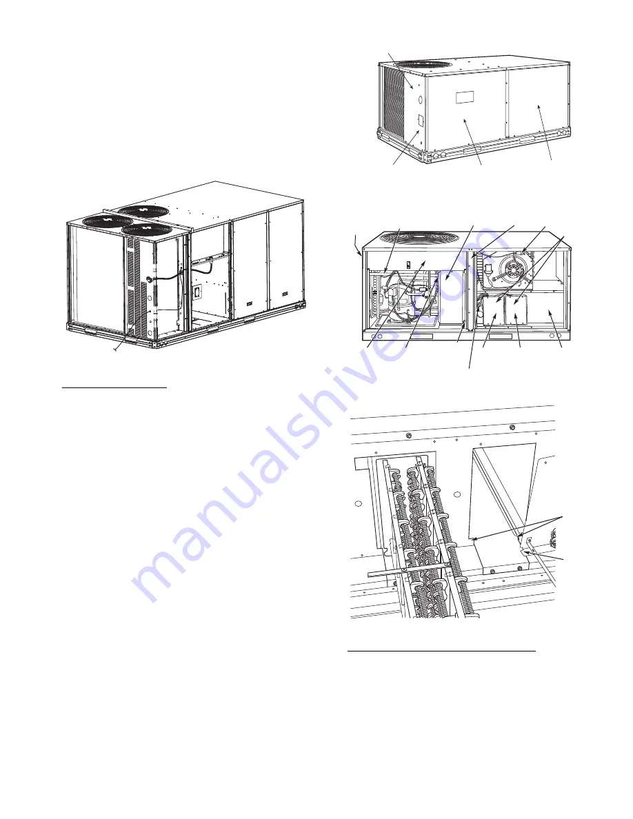
Heater modules are installed in the compartment below the
indoor (supply) fan outlet. Access is through the indoor access
panel. Heater modules slide into the compartment on tracks
along the bottom of the heater opening. See Fig. 52-54.
Not all available heater modules may be used in every unit.
Use only those heater modules that are UL listed for use in a
specific size unit. Refer to the label on the unit cabinet for the
list of approved heaters.
Unit heaters are marked with Heater Model Numbers. But
heaters are ordered as and shipped in cartons marked with a
corresponding heater Sales Package part number.
NOTE: The value in position 9 of the part number differs be-
tween the sales package part number (value is 1) and a bare
heater model number (value is 0).
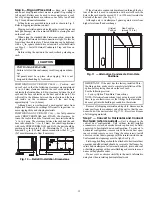
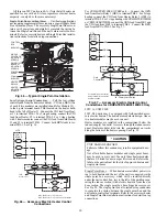
Fig. 52 — Typical Access Panel Location
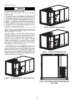
Fig. 53 — Typical Component Location
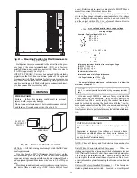
Fig. 54 — Typical Module Installation
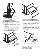
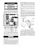
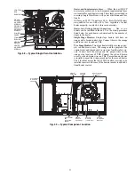
Single Point Boxes and Supplementary Fuses — When the
unit MOCP device value exceeds 60-A, unit-mounted supple-
mentary fuses are required for each heater circuit. These fuses
are included in accessory Single Point Boxes, with power dis-
tribution and fuse blocks. The single point box will be installed
directly under the unit control box, just to the left of the parti-
tion separating the indoor section (with electric heaters) from
the outdoor section. The Single Point Box has a hinged access
cover. See Fig. 55. The Single Point Box also includes a set of
power taps and pigtails to complete the wiring between the Sin-
gle Point Box and the unit’s main control box terminals. Refer
to the accessory heater and Single Point Box installation in-
structions for details on tap connections.
DISCONNECT MOUNTING
LOCATION
UNIT BLOCK-OFF
PANEL
OUTDOOR
ACCESS PANEL
INDOOR
ACCESS
PANEL
DISCONNECT
MOUNTING
LOCATION
EMT OR RIGID CONDUIT
(FIELD-SUPPLIED)
SINGLE
POINT BOX
CENTER
POST
HEATER
COVERS
HEATER
MOUNTING
BRACKET
HEATER
MODULE
(LOCATION 2)
HEATER
MODULE
(LOCATION 1)
SINGLE POINT
BOX
MOUNTING
SCREW
BRACKET AND
CONDUIT
DRIP BOOT
MAIN
CONTROL
BOX
CONTROL WIRE TERMINAL BLOCK
MANUAL RESET
LIMIT SWITCH
TRACK
FLANGE
Содержание Carrier WeatherMaker 50TC A08 Series
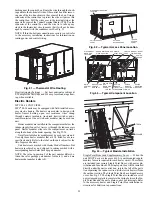
Страница 4: ...4 Fig 2 Unit Dimensional Drawing Size 08 09 12 Units...
Страница 5: ...5 Fig 2 Unit Dimensional Drawing Size 08 09 12 Units cont...
Страница 6: ...6 Fig 3 Unit Dimensional Drawing Size 14 Unit...
Страница 7: ...7 Fig 3 Unit Dimensional Drawing Size 14 Unit cont...
Страница 9: ...9 Fig 4 Unit Dimensional Drawing Size 16 Unit cont...
Страница 13: ...13 Fig 8 Roof Curb Details Size 16 Unit...
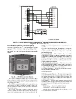
Страница 33: ...33 Fig 62 Typical Humidi MiZer Adaptive Dehumidification System Humidistat Wiring 50TC 08 14 Unit Sizes...
Страница 34: ...34 Fig 63 Typical Humidi MiZer Adaptive Dehumidification System Humidistat Wiring 50TC 16 Unit Sizes HUMIDISTAT...
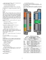
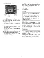
Страница 50: ...50 Fig 73 50TC 16 Control Box Component PremierLink Locations...
Страница 51: ...51 Fig 74 Typical PremierLink Control Wiring Diagram...
Страница 52: ...52 Fig 75 Typical PremierLink Control Wiring Diagram with Humidi MiZer System Option...
Страница 64: ...64 Fig 106 Typical RTU Open Controller Wiring Diagram 50TC 08 14 Size Units...
Страница 65: ...65 Fig 107 Typical RTU Open Controller Wiring Diagram 50TC 16 Size Unit...
Страница 66: ...66 Fig 108 Typical RTU Open Controller Wiring Diagram with Humidi MiZer System Option 50TC 08 14 Size Units...
Страница 67: ...67 Fig 109 Typical RTU Open Controller Wiring Diagram with Humidi MiZer System Option 50TC 16 Size Units...