
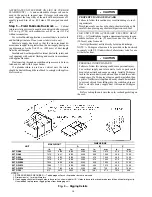


23
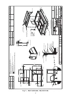
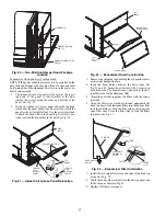
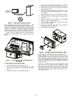
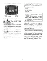
Fig. 34 — Thru-Base Connection Fittings
Check tightness of connector lock nuts before connecting
electrical conduits.
Field-supplied and field-installed liquid-tight conduit con-
nectors and conduit may be attached to the connectors on the
basepan. Pull correctly rated high voltage and low voltage
through appropriate conduits. Connect the power conduit to the
internal disconnect (if unit is so equipped) or to the external
disconnect (through unit side panel). A hole must be field cut in
the main control box bottom on the left side so the 24-v control
connections can be made. Connect the control power conduit to
the unit control box at this hole.
Units Without Thru-Base Connections
1. Install power wiring conduit through side panel openings.
Install conduit between disconnect and control box.
2. Install power lines to terminal connections as shown in
Field Control Wiring — The 50TC unit requires an external
temperature control device. This device can be a thermostat
(field-supplied) or a PremierLink™ controller (available as
factory-installed option or as field-installed accessory, for use
on a Carrier Comfort Network
®
or as a stand alone control) or
the RTU Open Controller for Building Management Systems
using non-CCN protocols (RTU Open is available as a factory-
installed option only).
Thermostat — Install a Carrier-approved accessory thermostat
according to installation instructions included with the accesso-
ry. For complete economizer function, select a two-stage cool-
ing thermostat. Locate the thermostat accessory on a solid wall
in the conditioned space to sense average temperature in accor-
dance with the thermostat installation instructions.
If the thermostat contains a logic circuit requiring 24-v power,
use a thermostat cable or equivalent single leads of different
colors with minimum of seven leads. If the thermostat does not
require a 24-v source (no “C” connection required), use a ther-
mostat cable or equivalent with minimum of six leads. Check
the thermostat installation instructions for additional features
which might require additional conductors in the cable.
For wire runs up to 50 ft. (15 m), use no. 18 AWG (American
Wire Gage) insulated wire [35°C (95°F) minimum]. For 50 to
75 ft. (15 to 23 m), use no. 16 AWG insulated wire [35°C
(95°F) minimum]. For over 75 ft. (23 m), use no. 14 AWG
insulated wire [35°C (95°F) minimum]. All wire sizes larger
than no. 18 AWG cannot be directly connected to the thermo-
stat and will require a junction box and splice at the thermostat.
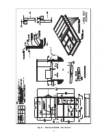
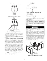
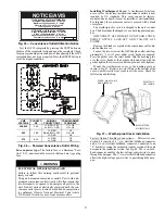
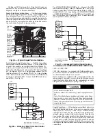
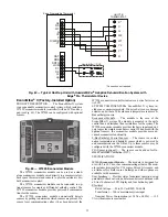
Fig. 35 — Typical Low-Voltage Control
Connections
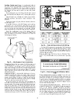
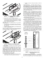
Unit without Thru-Base Connection Kit — Pass the thermo-
stat control wires through the hole provided in the corner post;
then feed the wires through the raceway built into the corner
post to the control box. Pull the wires over to the terminal strip
on the upper-left corner of the Controls Connection Board. See
Fig. 36 — Field Control Wiring Raceway
NOTE: If thru-the-bottom connections accessory is used, refer
to the accessory installation instructions for information on
routing power and control wiring.
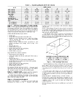
Heat Anticipator Settings — Set heat anticipator settings at
0.14 amp for the first stage and 0.14 amp for second-stage heat-
ing, when available.
LOW VOLTAGE
CONDUIT
CONNECTOR
HIGH VOLTAGE
CONDUIT
CONNECTOR
Typical
Thermostat
Connections
Central
Terminal
Board
W1
Y2
Y1
R
W2
G
C
X
W1
Y2
Y1
R
W2
G
C
X
T–STAT
C
W2
G
W1
O/B/Y2
R
Y1
(Note 1)
Note 1: Typical multi-function marking. Follow manufacturer’s configuration
instructions to select Y2.
Note 2: W2 connection not required on units with single-stage heating.
Field Wiring
(Note 2)
RACEWAY
HOLE IN END PANEL (HIDDEN)
Содержание Carrier WeatherMaker 50TC A08 Series
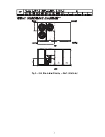
Страница 4: ...4 Fig 2 Unit Dimensional Drawing Size 08 09 12 Units...
Страница 5: ...5 Fig 2 Unit Dimensional Drawing Size 08 09 12 Units cont...
Страница 6: ...6 Fig 3 Unit Dimensional Drawing Size 14 Unit...
Страница 7: ...7 Fig 3 Unit Dimensional Drawing Size 14 Unit cont...
Страница 9: ...9 Fig 4 Unit Dimensional Drawing Size 16 Unit cont...
Страница 13: ...13 Fig 8 Roof Curb Details Size 16 Unit...
Страница 33: ...33 Fig 62 Typical Humidi MiZer Adaptive Dehumidification System Humidistat Wiring 50TC 08 14 Unit Sizes...
Страница 34: ...34 Fig 63 Typical Humidi MiZer Adaptive Dehumidification System Humidistat Wiring 50TC 16 Unit Sizes HUMIDISTAT...
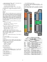
Страница 50: ...50 Fig 73 50TC 16 Control Box Component PremierLink Locations...
Страница 51: ...51 Fig 74 Typical PremierLink Control Wiring Diagram...
Страница 52: ...52 Fig 75 Typical PremierLink Control Wiring Diagram with Humidi MiZer System Option...
Страница 64: ...64 Fig 106 Typical RTU Open Controller Wiring Diagram 50TC 08 14 Size Units...
Страница 65: ...65 Fig 107 Typical RTU Open Controller Wiring Diagram 50TC 16 Size Unit...
Страница 66: ...66 Fig 108 Typical RTU Open Controller Wiring Diagram with Humidi MiZer System Option 50TC 08 14 Size Units...
Страница 67: ...67 Fig 109 Typical RTU Open Controller Wiring Diagram with Humidi MiZer System Option 50TC 16 Size Units...