


21
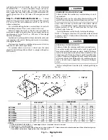
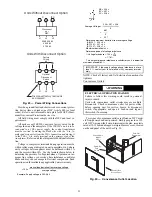
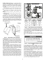
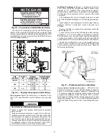
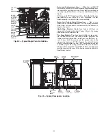
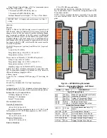
Fig. 29 — Power Wiring Connections
Provide a ground-fault and short-circuit over-current protec-
tion device (fuse or breaker) per NEC Article 440 (or local
codes). Refer to unit informative data plate for MOCP (Maxi-
mum Over-current Protection) device size.
All field wiring must comply with the NEC and local re-
quirements.
All units except 208/230-v units are factory wired for the
voltage shown on the nameplate.
If the 208/230-v unit is to be
connected to a 208-v power supply, the control transformer
must be rewired by moving the black wire with the
1
/
4
-in. fe-
male spade connector from the 230-v connection and moving it
to the 200-v
1
/
4
-in. male terminal on the primary side of the
transformer.
Refer to unit label diagram for additional informa-
tion.
Voltage to compressor terminals during operation must be
within voltage range indicated on unit nameplate. On 3-phase
units, voltages between phases must be balanced within 2%
and the current within 10%. Use the formula shown below to
determine the percent of voltage imbalance. Operation on im-
proper line voltage or excessive phase imbalance constitutes
abuse and may cause damage to electrical components. Such
operation would invalidate any applicable Carrier warranty.
Example: Supply voltage is 230-3-60.
AB = 224 v
BC = 231 v
AC = 226 v
Determine maximum deviation from average voltage.
(AB) 227
–
224 = 3 v
(BC) 231
–
227 = 4 v
(AC) 227
–
226 = 1 v
Maximum deviation is 4 v.
Determine percent of voltage imbalance.
% Voltage Imbalance = 100 x
= 1.76%
This amount of phase imbalance is satisfactory as it is below the
maximum allowable 2%.
NOTE: Check all factory and field electrical connections for
tightness.
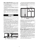
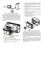
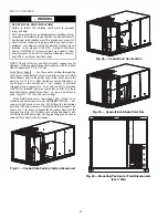
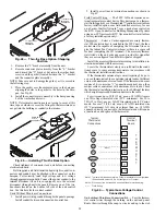
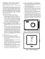
Convenience Outlets
Two types of convenience outlets are offered on 50TC mod-
els: Non-powered and unit-powered. Both types provide a 125-
volt GFCI (ground-fault circuit-interrupter) duplex receptacle
rated at 15-A behind a hinged waterproof access cover, located
on the end panel of the unit. See Fig. 30.
Fig. 30 — Convenience Outlet Location
= 100 x
max voltage deviation from average voltage
average voltage
C
IFC
Disconnect factory test leads
and discard.
13
13
L1
L2
L3
208/230-3-60
460-3-60
575-3-60
Units Without Disconnect Option
Units With Disconnect Option
1
3
5
2
4
6
L1
L2
L3
Factory
Wiring
Disconnect
per
NEC
Optional
Disconnect
Switch
11
Average Voltage =
224 + 231 + 226
3
=
681
3
=
227
IMPORTANT: If the supply voltage phase imbalance is more
than 2%, contact your local electric utility company immedi-
ately.
WARNING
ELECTRICAL OPERATION HAZARD
Failure to follow this warning could result in personal
injury or death.
Units with convenience outlet circuits may use multiple
disconnects. Check convenience outlet for power status
before opening unit for service. Locate its disconnect
switch, if appropriate, and open it. Lock-out and tag-out
this switch, if necessary.
4
226
Convenience
O
u
tlet
GFCI
Pwd-CO
F
us
e
S
witch
Pwd-CO
Tr
a
n
s
former
Control Box
Acce
ss
P
a
nel
Содержание Carrier WeatherMaker 50TC A08 Series
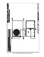
Страница 4: ...4 Fig 2 Unit Dimensional Drawing Size 08 09 12 Units...
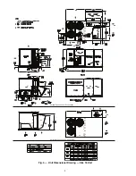
Страница 5: ...5 Fig 2 Unit Dimensional Drawing Size 08 09 12 Units cont...
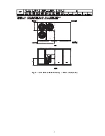
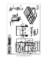
Страница 6: ...6 Fig 3 Unit Dimensional Drawing Size 14 Unit...
Страница 7: ...7 Fig 3 Unit Dimensional Drawing Size 14 Unit cont...
Страница 9: ...9 Fig 4 Unit Dimensional Drawing Size 16 Unit cont...
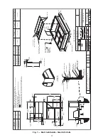
Страница 13: ...13 Fig 8 Roof Curb Details Size 16 Unit...
Страница 33: ...33 Fig 62 Typical Humidi MiZer Adaptive Dehumidification System Humidistat Wiring 50TC 08 14 Unit Sizes...
Страница 34: ...34 Fig 63 Typical Humidi MiZer Adaptive Dehumidification System Humidistat Wiring 50TC 16 Unit Sizes HUMIDISTAT...
Страница 50: ...50 Fig 73 50TC 16 Control Box Component PremierLink Locations...
Страница 51: ...51 Fig 74 Typical PremierLink Control Wiring Diagram...
Страница 52: ...52 Fig 75 Typical PremierLink Control Wiring Diagram with Humidi MiZer System Option...
Страница 64: ...64 Fig 106 Typical RTU Open Controller Wiring Diagram 50TC 08 14 Size Units...
Страница 65: ...65 Fig 107 Typical RTU Open Controller Wiring Diagram 50TC 16 Size Unit...
Страница 66: ...66 Fig 108 Typical RTU Open Controller Wiring Diagram with Humidi MiZer System Option 50TC 08 14 Size Units...
Страница 67: ...67 Fig 109 Typical RTU Open Controller Wiring Diagram with Humidi MiZer System Option 50TC 16 Size Units...