


15
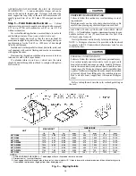
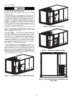
Step 6 — Rig and Place Unit —
Keep unit upright
and do not drop. Spreader bars are not required if top crating is
left on unit. Rollers may be used to move unit across a roof.
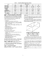
Level by using unit frame as a reference. See Table 1 and 2 and
Fig. 9 for additional information.
Lifting holes are provided in base rails as shown in Fig. 9.
Refer to rigging instructions on unit.
Rigging materials under unit (cardboard or wood to prevent
base pan damage) must be removed PRIOR to placing the unit
on the roof curb.
When using the standard side drain connection, ensure the
red plug in the alternate bottom connection is tight. Do this be-
fore setting the unit in place. The red drain pan can be tightened
with a
1
/
2
-in. square socket drive extension. For further details
see Step 9 — Install External Condensate Trap and Line on
Before setting the unit onto the curb, recheck gasketing on
curb.
POSITIONING ON CURB (50TC 08-14) — Position unit
on roof curb so that the following clearances are maintained:
1
/
4
in. (6.4 mm) clearance between the roof curb and the base
rail inside the front and back, 0.0 in. clearance between the roof
curb and the base rail inside on the duct end of the unit. This
will result in the distance between the roof curb and the base
rail inside on the condenser end of the unit being
approximately
1
/
4
in. (6.4 mm).
Although unit is weatherproof, guard against water from
higher level runoff and overhangs. After unit is in position, re-
move rigging skids and shipping materials.
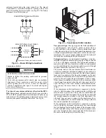
POSITIONING ON CURB (50TC 16) — For full perimeter
curbs CRRFCURB074A00 and 075A00, the clearance be-
tween the roof curb and the front and rear base rails should be
1
/
4
in. (6.4 mm). The clearance between the curb and the end
base rails should be
1
/
2
in. (13 mm). For retrofit applications
with curbs CRRFCURB003A01 and 4A01, the unit should be
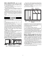
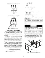
positioned as shown in Fig. 10. Maintain the 15
1
/
2
in. (394
mm) and 8
5
/
8
in. (220 mm) clearances and allow the 22
5
/
16
in.
(567 mm) dimension to float if necessary.
Fig. 10 — Retrofit Installation Dimensions
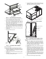
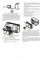
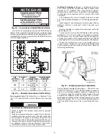
If the alternative condensate drain location through the bot-
tom of the unit is used in conjunction with a retrofit curb, the
hole in the curb must be moved 12.5 in. (320 mm) towards the
duct end of the unit. (See Fig. 11.)
Although unit is weatherproof, guard against water from
higher level runoff and overhangs.
Fig. 11 — Alternative Condensate Drain Hole
Positions
Remove all shipping materials and top skid. Remove extra
center post from the condenser end of the unit so that the con-
denser end of the unit matches Fig. 37-39. Recycle or dispose
of all shipping materials.
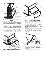
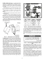
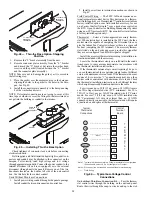
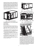
Step 7 — Convert to Horizontal and Connect
Ductwork (when required) —
Unit is shipped in the
vertical duct configuration. Unit without factory-installed
economizer or return air smoke detector option may be field-
converted to horizontal ducted configuration. To convert to
horizontal configuration, remove screws from side duct open-
ing covers and remove covers. Using the same screws, install
covers on vertical duct openings with the insulation-side down.
Seals around duct openings must be tight. See Fig. 12.
Field-supplied flanges should be attached to horizontal duct
openings and all ductwork should be secured to the flanges. In-
sulate and weatherproof all external ductwork, joints, and roof
or building openings with counter flashing and mastic in accor-
dance with applicable codes.
Do not cover or obscure visibility to the unit’s informative
data plate when insulating horizontal ductwork.
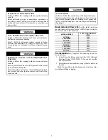
CAUTION
UNIT DAMAGE HAZARD
Failure to follow this caution may result in equipment dam-
age.
All panels must be in place when rigging. Unit is not
designed for handling by fork truck.
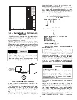
IMPORTANT: If the unit has the factory-installed Thru-
the-Base option, make sure to complete installation of the
option before placing the unit on the roof curb.
See the following section:
• Factory-Option Thru-Base Connections
NOTE: If electrical connections is not going to occur at this
time, tape or otherwise cover the fittings so that moisture
does not get into the building or conduit in the interim.
Original
Position
New Position
(moved 12.5 in.)
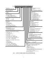
Содержание Carrier WeatherMaker 50TC A08 Series
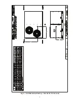
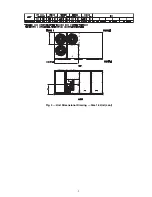
Страница 4: ...4 Fig 2 Unit Dimensional Drawing Size 08 09 12 Units...
Страница 5: ...5 Fig 2 Unit Dimensional Drawing Size 08 09 12 Units cont...
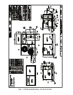
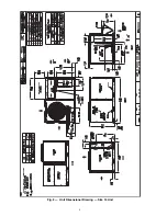
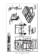
Страница 6: ...6 Fig 3 Unit Dimensional Drawing Size 14 Unit...
Страница 7: ...7 Fig 3 Unit Dimensional Drawing Size 14 Unit cont...
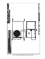
Страница 9: ...9 Fig 4 Unit Dimensional Drawing Size 16 Unit cont...
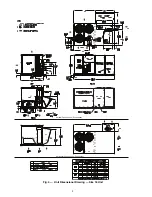
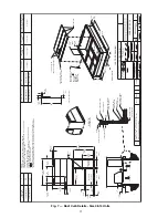
Страница 13: ...13 Fig 8 Roof Curb Details Size 16 Unit...
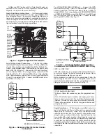
Страница 33: ...33 Fig 62 Typical Humidi MiZer Adaptive Dehumidification System Humidistat Wiring 50TC 08 14 Unit Sizes...
Страница 34: ...34 Fig 63 Typical Humidi MiZer Adaptive Dehumidification System Humidistat Wiring 50TC 16 Unit Sizes HUMIDISTAT...
Страница 50: ...50 Fig 73 50TC 16 Control Box Component PremierLink Locations...
Страница 51: ...51 Fig 74 Typical PremierLink Control Wiring Diagram...
Страница 52: ...52 Fig 75 Typical PremierLink Control Wiring Diagram with Humidi MiZer System Option...
Страница 64: ...64 Fig 106 Typical RTU Open Controller Wiring Diagram 50TC 08 14 Size Units...
Страница 65: ...65 Fig 107 Typical RTU Open Controller Wiring Diagram 50TC 16 Size Unit...
Страница 66: ...66 Fig 108 Typical RTU Open Controller Wiring Diagram with Humidi MiZer System Option 50TC 08 14 Size Units...
Страница 67: ...67 Fig 109 Typical RTU Open Controller Wiring Diagram with Humidi MiZer System Option 50TC 16 Size Units...