


16
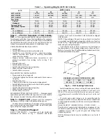
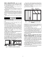
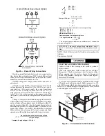
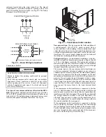
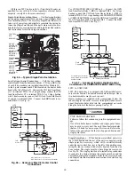
Fig. 12 — Horizontal Conversion Panels
Step 8 — Install Outside Air Hood
50TC 08-14 UNIT SIZES
Economizer and Two Position Damper Hood Package
Removal and Setup
(
Factory Option)
1. The hood is shipped in knock-down form and must be
field assembled. The indoor coil access panel is used as
the hood top while the hood sides, divider and filter are
packaged together, attached to a metal support tray using
plastic stretch wrap, and shipped in the return air com-
partment behind the indoor coil access panel. The hood
assembly’s metal tray is attached to the basepan and also
attached to the damper using two plastic tie-wraps.
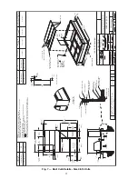
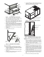
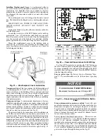
2. To gain access to the hood, remove the filter access panel.
Fig. 13 — Typical Access Panel Locations
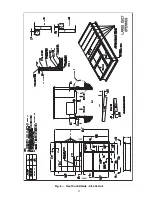
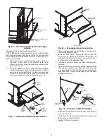
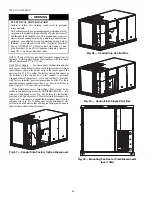
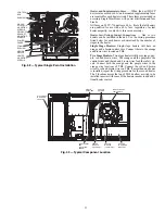
3. Locate the (2) screws holding the metal tray to the base-
pan and remove. Locate and cut the (2) plastic tie-wraps
securing the assembly to the damper. (See Fig. 14) Be
careful to not damage any wiring or cut tie-wraps secur-
ing any wiring.
4. Carefully lift the hood assembly (with metal tray) through
the filter access opening and assemble per the steps out-
lined in
Economizer Hood and Two-Position Damper
Hood.
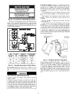
Fig. 14 — Economizer and Two-Position Damper
Hood Parts Location
Economizer Hood and Two-Position Damper Hood
NOTE: If the power exhaust accessory is to be installed on the
unit, the hood shipped with the unit will not be used and must
be discarded. Save the aluminum filter for use in the power
exhaust hood assembly.
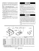
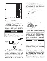
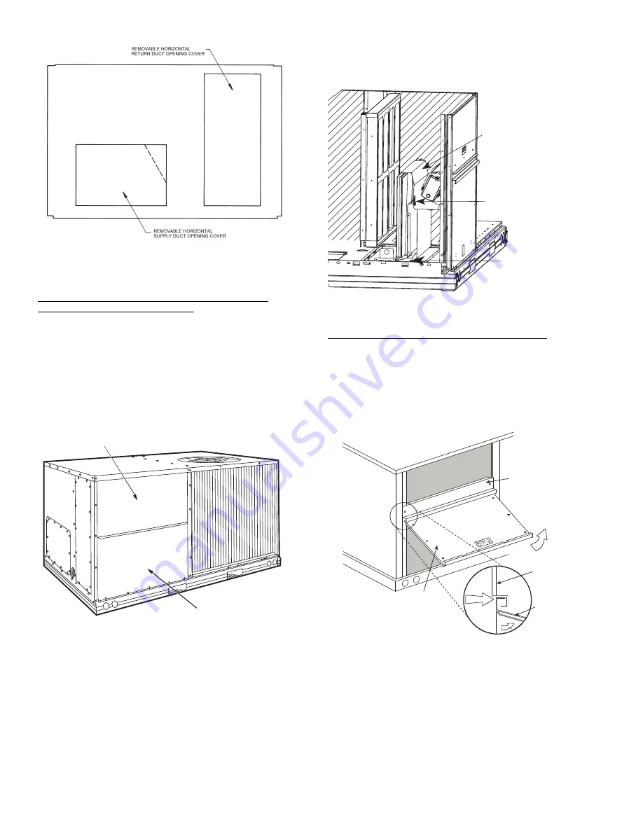
1. The indoor coil access panel will be used as the top of the
hood. Remove the screws along the sides and bottom of
the indoor coil access panel. See Fig. 15.
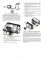
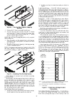
Fig. 15 — Indoor Coil Access Panel Relocation
2. Swing out indoor coil access panel and insert the hood
sides under the panel (hood top). Use the screws provided
to attach the hood sides to the hood top. Use screws pro-
vided to attach the hood sides to the unit. See Fig. 16.
FILTER ACCESS PANEL
INDOOR COIL ACCESS PANEL
Hood Parts
Plastic Tie Wrap
Qty (2)
Screws for Metal Tray
Qty (2)
TOP
PANEL
INDOOR
COIL
ACCESS
PANEL
INDOOR
COIL
ACCESS
PANEL
CAULK
HERE
TOP
PANEL
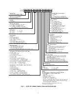
Содержание Carrier WeatherMaker 50TC A08 Series
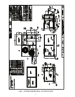
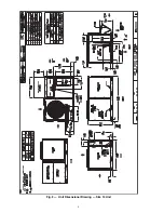
Страница 4: ...4 Fig 2 Unit Dimensional Drawing Size 08 09 12 Units...
Страница 5: ...5 Fig 2 Unit Dimensional Drawing Size 08 09 12 Units cont...
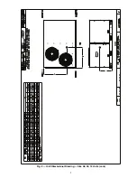
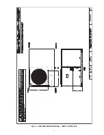
Страница 6: ...6 Fig 3 Unit Dimensional Drawing Size 14 Unit...
Страница 7: ...7 Fig 3 Unit Dimensional Drawing Size 14 Unit cont...
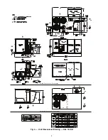
Страница 9: ...9 Fig 4 Unit Dimensional Drawing Size 16 Unit cont...
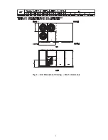
Страница 13: ...13 Fig 8 Roof Curb Details Size 16 Unit...
Страница 33: ...33 Fig 62 Typical Humidi MiZer Adaptive Dehumidification System Humidistat Wiring 50TC 08 14 Unit Sizes...
Страница 34: ...34 Fig 63 Typical Humidi MiZer Adaptive Dehumidification System Humidistat Wiring 50TC 16 Unit Sizes HUMIDISTAT...
Страница 50: ...50 Fig 73 50TC 16 Control Box Component PremierLink Locations...
Страница 51: ...51 Fig 74 Typical PremierLink Control Wiring Diagram...
Страница 52: ...52 Fig 75 Typical PremierLink Control Wiring Diagram with Humidi MiZer System Option...
Страница 64: ...64 Fig 106 Typical RTU Open Controller Wiring Diagram 50TC 08 14 Size Units...
Страница 65: ...65 Fig 107 Typical RTU Open Controller Wiring Diagram 50TC 16 Size Unit...
Страница 66: ...66 Fig 108 Typical RTU Open Controller Wiring Diagram with Humidi MiZer System Option 50TC 08 14 Size Units...
Страница 67: ...67 Fig 109 Typical RTU Open Controller Wiring Diagram with Humidi MiZer System Option 50TC 16 Size Units...