background image


      W A S H  

S E L E C T  

I I  

T O  

W A S H P A Y  


Document Number: 

WS21046 


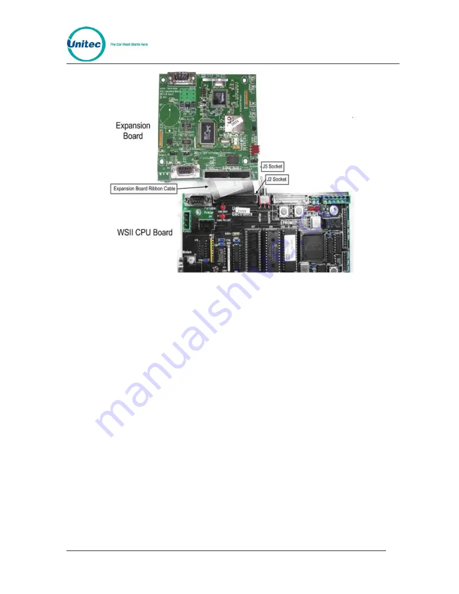
Figure 2. Expansion and CPU Board Layout 

1.  Ensure the main power to the WS2 is turned off. 

2.  Locate the Expansion Board mounting studs on the inside right wall. 

3.  Attach the included 4-40 male/female standoffs. 

4.  Attach the Expansion Board to the standoffs using the included white nylon 

plastic 4-40 nuts and washers. 

5.  Connect the ribbon cable from socket J5 on the Expansion Board to socket J2 

on the CPU Board.   

6.  Connect the CAT5 cable to the RJ45 jack on the board. 

3.5  WSII Software Upgrade Procedures 

To upgrade the WSII software, perform the following procedures: 

1.  Remove the existing EPROM located at connection U58 on the CPU board 

(see  Figure 3) by inserting a small flat-blade screwdriver between the 
EPROM and the socket and prying it off. Be careful not to damage the 
socket or the circuit board. 

Document Name: 

WSII to WashPayIntegration Field Retrofit Installation Guide


Содержание Wash Select II

Страница 1: ...Wash Select II to WashPay Integration Field Retrofit Installation Guide Wash Select II Software Version 6 00 and above POS4000 Software Version 8 25 Unitec www StartwithUnitec com ...

Страница 2: ...g for assistance you must have the following information available Wash Select II Serial Number Distributor Name C O P Y R I G H T 2012 Unitec Incorporated All rights reserved No part of this book including text screen examples diagrams or icons may be reproduced or transmitted in any form by any means electronic photocopying recording or otherwise without prior written permission of Unitec Incorp...

Страница 3: ...wer to the Wash Select II 2 3 3 Installation Preparation 2 3 4 Installation Procedures 2 3 4 1 Expansion Board Installation Procedures 3 3 5 WSII Software Upgrade Procedures 4 3 6 Upgrade POS4000 EPROM 6 4 Networking 7 5 System Configuration 8 5 1 Wash Select II 8 5 2 WashPay Server Setup 9 5 2 1 General Site Information 9 5 2 2 Product Programming 9 5 2 3 Card Terminal Programming 9 5 2 4 Receipt...

Страница 4: ... A S H S E L E C T I I T O W A S H P A Y Document Number WS21046 iv Document Name WSII to WashPayIntegration Field Retrofit Installation Guide T H I S P A G E I N T E N T I O N A L L Y L E F T B L A N K ...

Страница 5: ...outer in the office C store to the Wash Select II The CAT5E cable should not be more than 250 feet in length 2 Retrofit Installation Procedures 2 1 Parts Checklist Prior to retrofitting the existing Wash Select II units verify that all parts in the WSII to WashPay Network Upgrade Kit are present WSII to WashPay Network Expansion Board Expansion Board Ribbon Cable 4 4 40 M F stand offs 4 4 40 Nuts ...

Страница 6: ...hat the power is off using a voltage meter Warning Ensure power is disconnected from Wash Select II before proceeding with the installation Shut the power off at the main panel box or breaker box and verify by checking to see if the unit is still powered down 3 3 Installation Preparation Prior to beginning the installation make sure you have done the following 1 Power off the WSII 2 Remove the Coi...

Страница 7: ...ment Number WS21046 3 Figure 1 WSII Component Locations 3 4 1 Expansion Board Installation Procedures To install the expansion board in the WSII unit follow these procedures Document Name WSII to WashPayIntegration Field Retrofit Installation Guide ...

Страница 8: ...and washers 5 Connect the ribbon cable from socket J5 on the Expansion Board to socket J2 on the CPU Board 6 Connect the CAT5 cable to the RJ45 jack on the board 3 5 WSII Software Upgrade Procedures To upgrade the WSII software perform the following procedures 1 Remove the existing EPROM located at connection U58 on the CPU board see Figure 3 by inserting a small flat blade screwdriver between the...

Страница 9: ...he chip away from you to bend the pins Lay chip on its other side and rock it away from you Repeat the above steps alternating sides of the chip until pins are at approximately a 90 degree angle and line up in the socket 3 The notched end of the chip goes up There is a silk screened image on the CPU board you can use to line up the notch correctly This image is labeled EPROM 4 Push the EPROM chip ...

Страница 10: ...sed Message configuration Perform the following steps to change console software EPROM 1 Disconnect all cables to the POS4000 console 2 Remove the plastic housing To do this you must remove 2 screws from the rear and 2 screws from the bottom of the unit 3 The upper chassis must be partially removed Remove the middle and front screws along the side of the metal chassis Loosen the rear two screws on...

Страница 11: ...he chip until the pins line up in the socket without forcing the legs to fit 7 Reconnect the power and printer connections and turn on the unit As the system powers up the message SOFTWARE UPGRADE will appear momentarily 8 After the unit is powered up you MUST then press the RESET BUTTON to reset the system 9 After pressing the reset button the display will prompt you to press 99 or 55 Press 55 10...

Страница 12: ...ress the key to enter 4 Set the Credit Mode to 6 This will automatically set the network parameters 5 Scroll to Network Parameters Press to select 6 You should see Rev WP2 XX the x is the most current version of software Press any key Press any key to continue If this message is not displayed make sure the LED light is lit on the expansion board by the Ethernet cable and make sure the ribbon cable...

Страница 13: ...ettings that an equipment owner may wish to change periodically This section of the manual describes the programmable features that are available For specific details on using these features see the Sierra Management Application Programming Manual on the manufacturer s website www StartwithUnitec com 5 2 1 General Site Information Site information should be set during installation and would not ty...

Страница 14: ...e set up through the Products page before it can be assigned to a device profile This feature will typically not be changed after installation Equipment Interface The Equipment Interface Set up page is used to configure the interface between the card terminal and existing coin box and the pulses per coin or bill These settings should only be changed by your distributor User Interface Set up The Us...

Страница 15: ...up for employees service personnel or others that may need access to the WashPay system The User Set up pages are used to create new user accounts and to edit or delete an existing account User privileges that can be assigned are arranged in groups as follows User Management Allows the user to set up and manage other user accounts Device Set Up Allows access to the device profile programming funct...

Страница 16: ...te owner WSII Pager ID WSII Description WashPay Alert ID WashPay Alert 1 Hopper low 16 Peripheral low 10 2 Hopper empty 17 Peripheral empty 4 Wash out of service 4 Auto Out Of Service 8 Printer paper 17 Peripheral empty 9 Printer power error 12 Peripheral error 10 Printer error 12 Peripheral error 11 Bill jam 13 Peripheral jammed 12 Bill stacker full 14 Peripheral full 13 Bill validator error 12 P...

Отзывы: