


035-20646-001 Rev. A (1004)
10
Unitary Products Group
SECTION V: ELECTRICAL POWER
Annual Fuel Utilization Efficiency (AFUE) numbers are determined in accordance with DOE Test procedures.
Wire size and over current protection must comply with the National Electrical Code (NFPA-70-latest edition) and all local codes.
The furnace shall be installed so that the electrical components are protected from water.
* Wire size and overcurrent protection must comply with the National Electric Code.
NOTES:
1. For altitudes above 2000 ft. (609 m) reduce capacity 4% for each 1000 ft. above sea level.
2. Wire size based on copper conductors, 140° F (60°C), 3% voltage drop.
3. Continuous return air temperature must not be below 55°F (12.8° C).
ELECTRICAL POWER CONNECTIONS
Field wiring to the unit must be grounded. Electric wires that are field
installed shall conform to the temperature limitation for 63°F (35°C) rise
wire when installed in accordance with instructions. Refer to Table 7 in
these instructions for specific furnace electrical data.
SUPPLY VOLTAGE CONNECTIONS
1.
Provide a power supply separate from all other circuits. Install
overcurrent protection and disconnect switch per local/national
electrical codes. The switch should be close to the unit for conve-
nience in servicing. With the disconnect or fused switch in the OFF
position, check all wiring against the unit wiring label. Refer to the
wiring diagram in this instruction.
2.
Remove the screws retaining the wiring box cover. Route the
power wiring through the opening in the unit into the junction box
with a conduit connector or other proper connection. In the junc-
tion box there will be three wires, a Black Wire, a White Wire and a
Green Wire. Connect the power supply as shown on the unit-wir-
ing label on the inside of the blower compartment door or the wir-
ing schematic in this section. The black furnace lead must be
connected to the L1 (hot) wire from the power supply. The white
furnace lead must be connected to neutral. Connect the green fur-
nace lead (equipment ground) to the power supply ground. An
alternate wiring method is to use a field provided 2” (5.08 cm) x 4”
(10.2 cm) box and cover on the outside of the furnace. Route the
furnace leads into the box using a protective bushing where the
wires pass through the furnace panel. After making the wiring con-
nections replace the wiring box cover and screws. Refer to Figure
10.
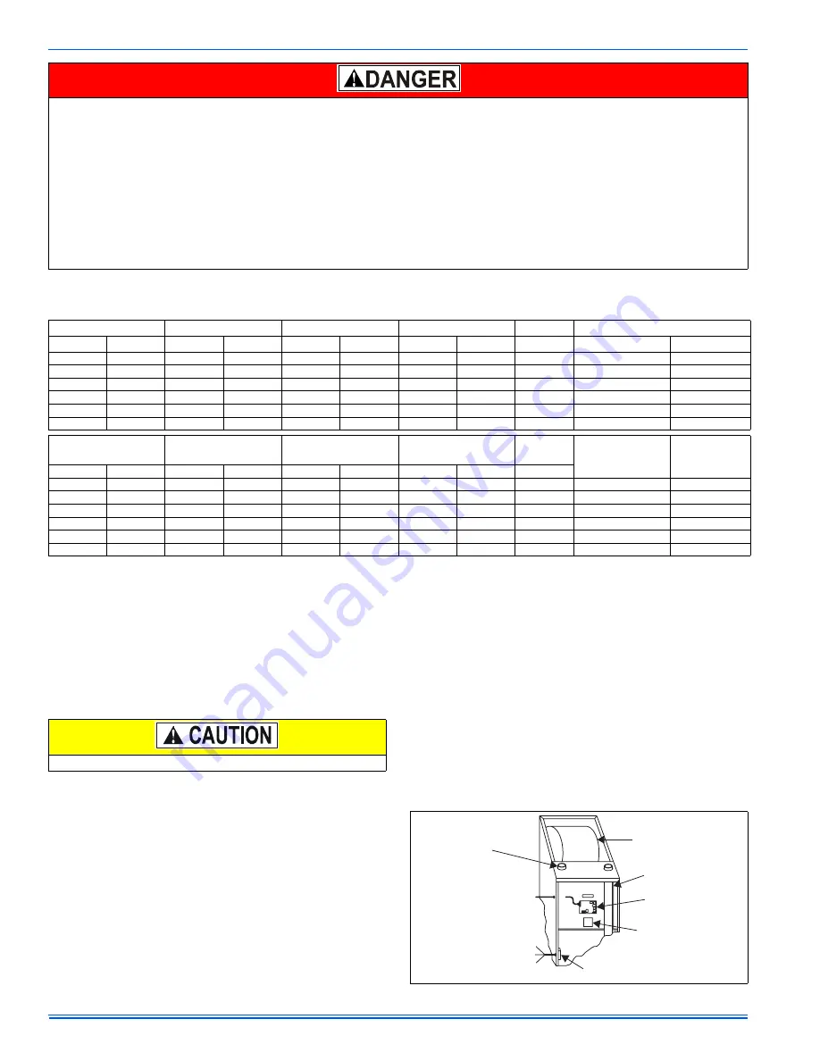
3.
The furnace's control system requires correct polarity of the power
supply and a proper ground connection. Refer to Figure 11.
IMPORTANT:
The power connection leads and wiring box may be relo-
cated to the left side of the furnace. Remove the screws and cut wire tie
holding excess wiring. Reposition on the left side of the furnace and fas-
ten using holes provided.
PROPANE AND HIGH ALTITUDE CONVERSION KITS
It is very important to choose the correct kit and/or gas orifices for the altitude and the type of gas for which the furnace is being installed.
Only use natural gas in furnaces designed for natural gas. Only use propane (LP) gas for furnaces that have been properly converted to use pro-
pane (LP) gas. Do not use this furnace with butane gas.
Incorrect gas orifices or a furnace that has been improperly converted will create an extremely dangerous condition resulting in premature heat
exchanger failure, excessive sooting, high levels of carbon monoxide, personal injury, property damage, a fire hazard and/or death.
High altitude and propane (LP) conversions are required in order for the appliance to satisfactory meet the application.
An authorized distributor or dealer must make all gas conversions.
In Canada, a certified conversion station or other qualified agency, using factory specified and/or approved parts, must perform the conversion.
The installer must take every precaution to insure that the furnace has been converted to the proper gas orifice size when the furnace is installed.
Do not attempt to drill out any orifices to obtain the proper orifice size. Drilling out a gas orifice will cause misalignment of the burner flames,
causing premature heat exchanger burnout, high levels of carbon monoxide, excessive sooting, a fire hazard, personal injury, property damage
and/or death.
TABLE 8:
Electrical and Performance Data
Input
Output
Nominal Airflow
Cabinet Width
AFUE
Air Temp. Rise
MBH
kW
MBH
kW
CFM
m
3
/min
In.
mm
%
°F
°C
60
18
55
16.1
1200
34.0
17-1/2
444
92
35 - 65
19 - 36
80
23
74
21.7
1200
34.0
17-1/2
444
91
35 - 65
19 - 36
80
23
74
21.7
1600
45.3
21
533
92
35 - 65
19 - 36
100
29
93
27.3
1600
45.3
21
533
92
35 - 65
19 - 36
100
29
93
27.3
2000
56.6
21
533
92
35 - 65
19 - 36
120
35
112
32.8
2000
56.6
24-1/2
622
92
35 - 65
19 - 36
Input
Max. Outlet
Air Temp.
Blower
Blower Size
Total Unit
Max.
Over-current
Protect
Min. Wire Size
(awg) @ 75 ft.
One Way
MBH kW
°F
°C
HP
Amps
In.
mm
Amps
60
18
170
76.7
1/2
7.0
11 x 8
279 x 203
9
20
14
80
23
165
76.7
1/2
7.0
11 x 8
279 x 203
9
20
14
80
23
170
76.7
3/4
10.2
11 x 10
279 x 254
12
20
14
100
29
165
79.4
3/4
10.2
11 x 10
254 x 254
12
20
14
100
29
165
79.4
1
12.7
11 x 11
279 x 279
14
20
12
120
35
165
76.7
1
12.7
11 x 11
279 x 279
14
20
12
Use copper conductors only.
FIGURE 11:
Electrical Wiring
(BLK) LI (HOT)
(WHT) N
(GRN)GND
JUNCTION
BOX
TRANSFORMER
BLOWER
COMPARTMENT
CLASS 2 SYSTEM
CONTROL WIRING
TO THERMOSTAT
COMBUSTION
AIR
VENT PIPE
IGNITION
MODULE