ACCESSORY KIT INSTALLATION MANUAL
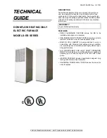
3500-8941 DOWNFLOW COIL SHELF AND CONDENSATE TRAP PACKAGE
USE WITH MODELS: EB**B SERIES AND EARLIER ELECTRIC FURNACES
Johnson Controls Unitary Products
18585-UAI-C-0708
IMPORTANT -
These instructions are intended for the use by
qualified service technician specially trained and experienced in
installation of this type of equipment and related system compo-
nents.
Installation and service personnel are required by some states
to be licensed.
Persons not qualified shall not install this equipment or interpret
these instructions.
NOTE:
The words “Shall" or “Must" indicate a requirement
which is essential to satisfactory and safe product performance.
The words “Should" or “May" indicate a recommendation or
advice which is not essential and not required but which may be
useful or helpful.
APPLICATION
The 3500-8941 Coil Shelf and Insulation Package is designed
for use on the EB**B Series & 3500 Series electric furnaces for
manufactured homes. This package is required when an air
conditioning or heat pump with an indoor coil is added to the
electric furnace in the downflow configuration.
Some modifications have been made to EB**B electric furnaces
to accept A-Coils with this accessory. All EB series furnaces
manufactured after August 1998 already have these changes
implemented. If this accessory is being installed with an older
EB series furnace, then refer to “Modification Required to Add
A/C to Older EB Furnaces” in these instructions, when adding
air conditioning to the furnace.
NOTE:
Use this coil shelf only in conjunction with Indoor Coils
from a manufacturer which incorporate an auxiliary overflow
tube on the drain pan.
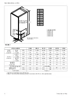
This package contains the following parts:
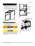
INSTALLATION OF COIL SUPPORT
1.
Remove furnace door.
2.
EB Series - Turn circuit breakers to "OFF". 3500 Series -
Pull furnace disconnect block.
3.
Remove the five blower mounting screws and slide the
blower 1/2 way out of the front of the furnace. (Save
mounting screws.).
4.
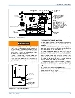
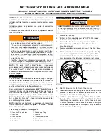
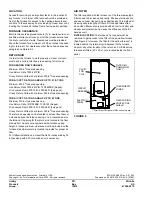
Remove wire clamp screw and remove wire tie. See Figure
1.
5.
Disconnect motor wires from motor and capacitor. See Fig-
ure 1. In some applications motor wires may have to be
disconnected inside the control box of the furnace. For
more information refer to furnace installation instructions.
6.
Slide the blower out of the front of the furnace.
7.
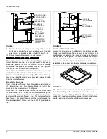
Install insulation tabs to casing sides and back with screws
provided. Screw holes for tabs are located below the two
sets of holes for coil cabinet. See Figure 2.
8.
Install insulation in furnace casing with coated side visible.
Tuck insulation inside casing front edge. Push insulation
tabs through the insulation. Be sure to fold tabs back over
to secure insulation to casing sides and back. See Figure
2. If needed, spray adhesive - 3M Super 77 may be used to
secure insulation to the casing.
Improper installation or service may damage equipment,
can create a hazard and will void the warranty.
The use of other components not tested in combination with
these units may make the equipment in violation of state
codes, may create a hazard and may ruin the equipment. In
addition, the National Mobile Home Construction and Safety
Standards Act and its regulations require the use of compo-
nents tested or certified by a nationally recognized testing
laboratory in all manufactured homes constructed or sold
subject to that act.
Carefully follow all instructions and warnings in this booklet
to avoid damage to the equipment, personal injury or fire.
1 - Insulation Side and Back
1 - Condensate Trap
1 - Coil Shelf
1 - Wire Tie
3 - Insulation Tabs
20 - Sheet Metal Screws
1 - Installation Manual
2 - Hose Clamps
1- Drain Tube
2 - Coil Shelf Panels (Insulated)
SHOCK HAZARD - Be sure to turn the electric power “OFF”
at the main electrical service entrance box, and lock it to
prevent the possibility of personal injury or damage to the
equipment.
FIGURE 1
WIRE CLAMP
WIRE TIE

