035-15266-003 Rev. A (0804)
10
Unitary Products Group
OPTIONAL AIR CONDITIONING
ACCESSORIES
This furnace is already equipped with a blower and control
system to add-on air conditioning up to 4 tons and heat pump
up to 3-1/2 tons. Insulation and coil shelf kit (3500-8941* for
downflow or 3500-8961* for upflow) must be installed when
adding on such remote air conditioning systems.
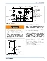
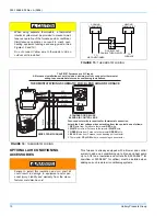
When using separate thermostats, a thermostat
interlock system must be provided to prevent simul-
taneous operation of the furnace and air conditioner.
Simultaneous operation can result in coach over-
heating, equipment damage and energy waste. (See
Figures 15 and 16.)
Do not connect Yellow wire to thermostat until an
outdoor unit is installed.
FIGURE 15 :
THERMOSTAT WIRING
COOLING
THERMOSTAT
HEATING
THERMOSTAT
TO
AIR CONDITIONER
TO
FURNACE
DOUBLE POLE
DOUBLE THROW SWITCH
FIGURE 16 :
THERMOSTAT WIRING
DELUXE BLEND AIR
II
FRESH
AIR
OFF
AUTO
ALARM
RED
RED
WHITE
WHITE
GREEN
GREEN
BLACK
BLACK
BLACK
RED
WHITE
GREEN
YELLOW
WIRES FROM FURNACE
NOT FACTORY
INSTALLED
STANDARD OR DELUXE
BLEND AIR CONTROL BOX
THERMOSTAT WIRING SCHEMATIC FOR: BLEND AIR AND FURNACE
The EB*B* Furnaces are A/C ready.
All furnaces installations should include a minimum of four conductor thermostat
wiring to accommodate future air conditioning installations.
Four-conductor wire is required for thermostat connection.
Attach the 4 low voltage wires extending from the control box as follows:
RED
RED
WHITE
WHITE
GREEN
GREEN
BLACK
YELLOW
1.
wire from Furnace to thermostat
wire.
2.
wire from Furnace to thermostat
wire.
3.
wire from Furnace to thermostat
wire.
4.
wire from Furnace to condensing unit contactor.
5. Thermostat
wire to condensing unit contactor.
Failure to install this insulation and coil shelf kit
could result in damage to equipment and/or per-
sonal injury. Liability and warranty from the manu-
facturer could also be void.


