


4.CALIBRATION
30
・
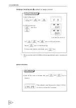
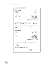
Calibration LOCK
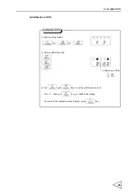
1) Select setting mode 3.
2) Select calibration lock.
3
)
Use
and
key to set the calibration lock of
ON
(
1
)
.
then use
key to validate the setting
To return to the indicated value display, press
key.
FNC
SEL
SEL
DOWN
ENT
SEL
UP
DOWN
ENT
ESC
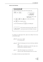
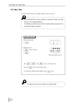
Calibration LOCK
1
:
ON
0
:
OFF
Calibration LOCK
Содержание F340A
Страница 1: ...F340A DIGITAL INDICATOR 14 Feb 2012 Rev 1 38 OPERATION MANUAL...
Страница 9: ...CONTENTS 15 7 General Specifications 90 15 8 Accessories 91 16 CONFORMITY TO EC DIRECTIVES 92...
Страница 92: ...13 SELF CHECK FUNCTION AND INITIALIZATION 83 Self check Visual Check Sequence...
Страница 94: ...13 SELF CHECK FUNCTION AND INITIALIZATION 85 Initialization Sequence...
Страница 104: ...Unipulse Corporation 9 11 Nihonbashi Hisamatsucho Chuo ku Tokyo 103 0005 Tel 81 3 3639 6120 Fax 81 3 3639 6130...