Page 9
DPU1U SERIES
INSTALLATION & OPERATING MANUAL
P O W E R I N G T E C H N O L O G Y
Document Number: DPU1U-MAN Rev. 4
dpu1u-man-rev1-0719.indd
8.0 FRONT PANEL DESCRIPTION
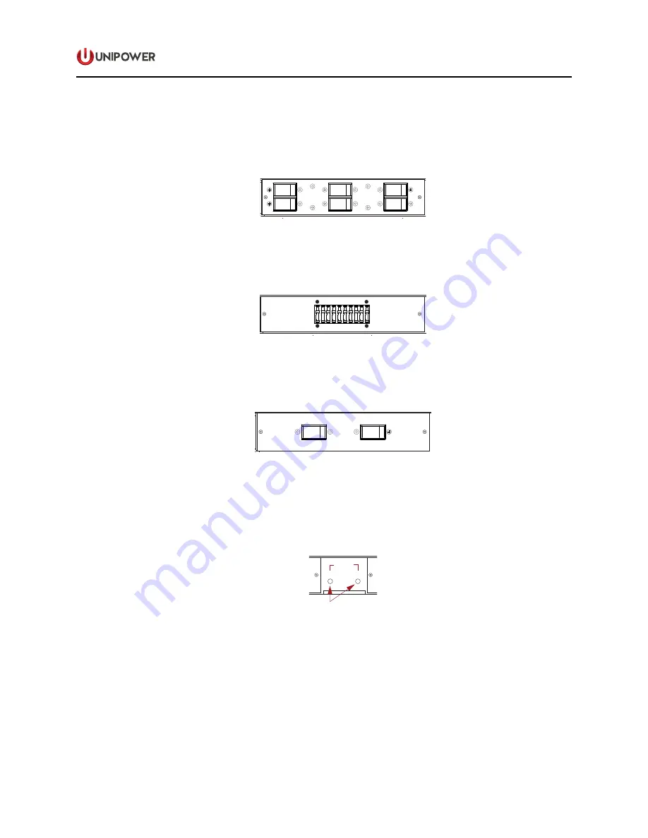
The front panel of the circuit breaker distribution section, shown in Figure 4 below, can accommodate
up to 6 hydraulic magnetic circuit breakers rated from 1A to 50A.
Alarm
Contacts
Alarm LEDs
B Input
¼-20 Studs
BAT
RTN
BAT
RTN
1 2 3 4 5 6 7 8 9 10
A
B
ALARM
Ground
8-32 Stud
A Side Breakers
B Side Breakers
A Outputs
6-32 Terminal Strip
B Outputs
6-32 Terminal Strip
A Input
¼-20 Studs
BAT
RTN
BAT
RTN
1 2 3 4 5 6 7 8 9 10
B SIDE A SIDE
NO-C-NC
NO-C-NC
5
6
3
4
1
2
OFF
O
ON
I
15
OFF
O
ON
I
15
OFF
O
ON
I
15
OFF
O
ON
I
15
OFF
O
ON
I
15
OFF
O
ON
I
15
5
6
3
4
1
2
OFF
O
ON
I
15
OFF
O
ON
I
15
OFF
O
ON
I
15
OFF
O
ON
I
15
OFF
O
ON
I
15
OFF
O
ON
I
15
17.12 (434.9)
1.74
(44.2)
REAR VIEW
FRONT VIEW
Case depth: 8.94 (227.1)
2.28
(57.8)
Clear Perspex
Safety Cover
Figure 4. Distribution Section Front Panel View
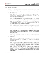
The front panel of the GMT fuse distribution section, shown in Figure 5 below, can each accommodate
up to 10 GMT Fuses rated from ½A to 12A.
Alarm LEDs
A
B
ALARM
A Side Fuses
B Side Fuses
1
10
1
10
17.12 (434.9)
FRONT VIEW
1.74
(44.2)
Figure 5. GMT Fuse Section Front Panel View
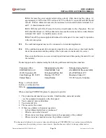
The front panel of the LVD section, shown in Figure 6 below, incorporates a 70A LVD hydraulic
magnetic circuit breaker and (optionally) a 70A ByPass magnetic circuit breaker.
A
B
ALARM
OFF
O
ON
I
70
OFF
O
ON
I
70
OFF
O
ON
I
70
OFF
O
ON
I
70
Figure 6. LVD Front Panel View
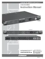
The center section has two green/red LEDs, one for the A side (left) and the other for the B side
(right). At the bottom of this center section is a slot for a wallet and designator card. This card
permits the recording of each output circuit by number.
Alarm LEDs
A
B
ALARM
A Side Fuses
B Side Fuses
1
10
1
10
17.12 (434.9)
FRONT VIEW
1.74
(44.2)
Figure 7. Center Section Front Panel View


