


P O W E R I N G T E C H N O L O G Y
North America & CALA: +1 954-346-2442 • EMEA: +1 561-990-3830 • [email protected]
DPU1U SERIES COMBINATION PANELS - 2
© 2019 UNIPOWER LLC
This document is believed to be correct at time of publication and Unipower LLC accepts no responsibility for consequences from printing errors or inaccuracies. All specifications subject to change without notice.
dpu
1u-
ds-r
ev
G-
09
19
.in
dd
SPECIFICATIONS
Typical at 25
°
C Unless Otherwise Noted.
INPUT / OUTPUT
Fuse & Breaker Capacity .....................................................................................80A or 150A Per Bus
LVD Capacity ........................................................................................................................................................70A
Fuse Configuration .................................................................................................................10 GMT Fuses
Breaker Configurations .....................................................................................................1 to 6 Breakers
Voltage
48V Nominal ..................................................................................................................................42-60VDC
24V Nominal ....................................................................................................................................21-30VDC
12V Nominal...................................................................................................................................10.5-15VDC
Polarity ..........................................................................................................Positive or Negative Ground
ALARMS
Alarm Indicator ................................................................................................................LED on Each Side
LED Status
Fuse & Breaker Sections .........................................................................................Green = Normal
Red = Alarm, Off = No Power
LVD Section ............................................ Red = LVD Contactor or Battery Breaker Open
Off = Normal
Alarm Connections
Fuse & Breaker .............................................................. Two Form C Relay Contacts Per Bus
LVD ..................................... Form C Relay Contacts for Disconnect or Battery Breaker
SAFETY STANDARDS
.........................................................UL1950, CSA22.2 No.950, EN60-950
ENVIRONMENTAL
Operating Temp. Range ....................................................................................................-10°C to +70°C
Storage Temp. Range .......................................................................................................-40°C to + 85°C
Humidity .....................................................................................................0% to 95%, Non-Condensing
PHYSICAL SPECIFICATIONS
Case Material ....................................................................................................................................................Steel
Finish .......................................................................................................................................Powder Coat Gray
Dimensions, Inches (mm) ........................................................................1.75 H x 19.00 W x 9.00 D
(44.5 x 483 x 229)
Weight ..........................................................................................................8.76 - 9.73 lbs. (3.97 - 4.41 kg.)
Rack Mounting Width ........................................................................................................19 or 23 Inches
CONNECTIONS
Input Connections....................................................................Crimp Type Lugs or ¼ - 20 Studs
Output Connections
Fuse or Breaker ............................................................................................. Barrier Terminal Strips
LVD .................................................................................................Crimp Type Lugs or ¼ - 20 Studs
Battery Connection, LVD .....................................................Crimp Type Lugs or ¼ - 20 Studs
Chassis Ground Connection ........................................................................................... No. 8-32 Stud
Alarm Connections ..................................................................................... 0.045” sq. Wirewrap Pins
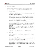
Notes:
1. As shown, only side B can have a low-voltage disconnect,
specified by “L”.
2. A bypass switch must also be designated YES or NO.
3. For a breaker panel, each breaker must be specified with
highest current in position 1 down to lowest current in
position 6.
Alarm
Contacts (see manual)
Alarm LEDs
¼-20 Studs
BAT
RTN
RECT
RTN
A
B
ALARM
Ground
8-32 Stud
A Side Breakers
B Side LVD
A Outputs
6-32 Terminal Strip
A Input
¼-20 Studs
BAT
RTN
BAT
RTN
1 2 3 4 5 6 7 8 9 10
5
6
3
4
1
2
OFF
O
ON
I
15
OFF
O
ON
I
15
OFF
O
ON
I
15
OFF
O
ON
I
15
OFF
O
ON
I
15
OFF
O
ON
I
15
OFF
O
ON
I
70
OFF
O
ON
I
70
BYPASS
BATTERY
LVD
¼-20 Studs
NO-C-NC
NO-C-NC
17.12 (434.9)
1.74
(44.2)
TYPICAL REAR VIEW
TYPICAL FRONT VIEW
Case depth: 8.94 (227.1)
2.28
(57.8)
Clear Perspex
Safety Cover
ALL DIMENSIONS IN INCHES (mm)
ORDERING GUIDE
CODE
OPTION
2
S
Bypass Switch
X
No Bypass Switch
CODE
VOLTAGE (POLARITY)
1
-48V (+Ve Ground)
2
+48V (-Ve Ground)
3
-24V (+Ve Ground)
4
+24V (-Ve Ground)
5
-12V (+Ve Ground)
6
+12V (-Ve Ground)
BREAKERS
3
CODE
AMPS
CODE
AMPS
F
1
K
20
G
2.5
L
25
H
5
M
30
I
10
N
40
J
15
O
50
Clear Plastic
Rear Safety Cover
(supplied as standard)
CODE
TYPE
G
GMT Fuses
B
Breakers
Model No.: DPU1U-A
-B
-C
-B
-
-C
(BREAKER PANEL ONLY)
(BREAKER PANEL ONLY)
L
LV DISCONNECT
1
INSTRUCTIONS
For each section (A or B) determine
the type and voltage and polarity. Use
codes from the tables. If a breaker
section is specified, insert breaker
currents into each box (from 1 to 6
breakers). The B section is specified
in the same way as the A section.
An LVD can only be specified for the
B section. For panels that are not
UNIFLEX
®
(combination), i.e., both
A and B are identical, order models
,
. Also for full
specifications on fuses, breaker or
LVD sections, refer to data sheets for
these products.
To order GMT fuses see
datasheet.
Crimp type lugs for the input and
battery connections should be
ordered separately.
For a kit of 4 two-hole lugs for #6 AWG
wire, order code
775-1434-0000
.
AVAILABLE CONFIGURATIONS