


User guide and technical documentation
Page
22
of
29
Note:
If DO is enabled, the PWM value is ignored. If the PWM value is other than 0 and the DO value switches
from 1 to 0, the PWM function becomes active.
The length of one T
c
cycle is set using the PWM Prescale and PWM Cycle variables. PWM Cycle is basically
the resolution of the PWM (the PWM value can take values from 0 to PWM Cycle). The calculation is described
by the following formula:
T
c
=
(PWM
prescale
+1)
48MHz
·(PWM
cycle
+1)
Alternative PWM Prescale calculation, where
f
is the selected PWM frequency in Hz.
Note that the result
must be rounded to an integer!
PWM
prescale
=
48MHz
f
∙
(PWM
cycle
+1)
1
Example:
Setting PWM Prescale to 4751 and PWM Cycle to 100, T
c
equals 10 ms (100 Hz). Furthermore, by
setting the PWM value to 50, the duty cycle will be 50 % at a frequency of 100 Hz.
3.4.3
Other setting and informative functions
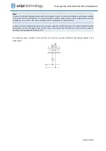
3.4.3.1
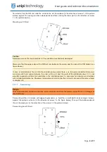
ULED
Some units feature freely programmable LEDs marked as X1 … Xn. Diode control is done through ULED
variables for each diode separately.
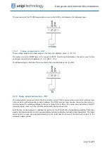
3.4.3.2
Disabling of 1-Wire bus
Units that include a 1-Wire bus also have a bus on/off function. By default, the value of the
Disable 1-Wire
Bus
variable is set to False, so the bus is turned on. Switching the value to True will turn off its power and
disconnect the 1-Wire bus.
3.4.3.3
Default settings
This function is used to save the current section configuration to its memory. When disconnecting from and
reconnecting to the power, or when restarting section, saved configuration is loaded and used. This feature
is also known as "copy running-config to startup-config".
Note:
The stored data are: Debounce, Counter, DirectSwitch, DO/RO output value, PWM configuration, AI
measurement mode (see chapter 2.4.7), AO mode and value (see chapter 2.4.8) and communication line
settings of the given section except for serial lines mapped to Linux as ttymxc (see chapter 3.3.1).
3.4.3.4
Master WatchDog (MWD)
This function runs on the section's microprocessor and continuously monitors the commands from the
application running on the unit. If no commands are detected within a configured time (MWD Timeout) and
MWD function is enabled (MWD Enable), the section's processor automatically resets to the default
configuration described in chapter 3.4.3.3 and sets the value indicating MWD Reset to True.
This function ensures the setting of a safe configuration in case of emergency situations, e.g. in the event of
a failure of the unit, interruption of communication, or problems with the software so as to prevent damage
to the controlled devices or danger to persons.
3.4.3.5
Reboot
Each section can be restarted by software.