


User guide and technical documentation
Page
17
of
29
3.1.2
Service mode
Service mode is a web tool for IP configuration, (de)activation of Mervis and SSH services, reflashing of OS
images, creation of OS backup to USB flash drive and other useful functions. To activate the service mode,
follow these steps:
1.
Remove any connected USB flash drives and connect the unit to a local network or directly to your
PC, using a network cable.
2.
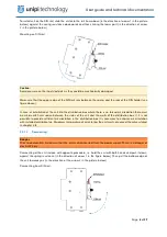
Press and
hold
the ”SERVICE“ button on the unit’s top side.
3.
Connect a power supply. All outputs are set to their default configuration, all outputs are disabled
by default.
4.
Patron will boot into a service mode indicated by slow blinking of all LEDs on section 1 (except PWR
and RUN). You can now release the button.
5.
The unit will set its own IP address to 192.168.200.200 while simultaneously attempting to obtain an
IP address from the DHCP server. The unit will be then available at both IP addresses.
6.
To access the service web interface, use a web browser and enter the IP address http://<ip-
address>.
3.1.2.1
Reflashing the OS
The operating system can be reflashed via the service web interface or by using a USB flash drive.
Download and extract the selected ZIP archive with Patron OS image from Knowledge Base
(
https://kb.unipi.technology
) to your PC or use files from USB backup.
Caution:
Reflashing will
delete all data stored in the unit’s onboard memory storage
.
3.1.2.2
Reflashing the OS using service web interface
1.
Switch the unit into the service mode (see above), indicated by slow blinking of all LEDs on section
1 (except PWR and RUN).
2.
Drag only the
archive.swu
file from the extracted archive and drop it into the Software Update
dialogue in the service web interface.
3.
Patron will start reflashing the OS, the process is indicated by rapid blinking of all LEDs on section
1 (except PWR and RUN).
4.
Wait until the process is finished – reflash progress can be seen in the Software Update dialogue.
5.
The unit will automatically reboot upon successful OS image reflashing procedure.
3.1.2.3
Reflashing the OS using USB flash drive
1.
Prepare an USB flash drive with at least 2 GB of free memory (FAT32 format).
2.
Copy all extracted files from OS image to the USB drive or use the USB flash drive with backup files.
3.
Insert the USB flash drive into one of unit’s USB port.
4.
Press and hold the ”SERVICE“ button on the unit’s top side.
5.
Connect power supply.
6.
Patron will start reflashing the OS, the process is indicated by rapid blinking of all LEDs on section
1 (except PWR and RUN). You may now release “SERVICE” the button.
7.
LEDs will stop blinking once the reflash is completed. The unit then automatically reboots.
Note:
Some USB flash drives may not be compatible. If your flash drive does not work, try another or reflash the
OS using service web interface.
3.1.2.4
Backup OS to USB flash drive
1.
Prepare a USB flash drive in FAT32 format with a capacity of at least 2 GB.
2.
Start the unit in the service mode described above.
3.
Click on the "Backup to USB flash" button in the dialog window under the "Backup" header in the
service web interface.
4.
The controller will start the OS backup indicated by the fast blinking of all LEDs on section 1 (except
PWR and RUN).