

UPS471-02-00 PW9000DPA User Manual UK Dated 06/08/14
35
3: Installation
3.7
UPS Cabling procedure
Safety notes
Please ensure you read and understand the following safety notes before you begin the UPS electrical installation.
1. Do not commence this procedure until the UPS mechanical installation is completed.
2. All the cable installation procedures detailed below must be supervised by a qualified electrician.
3. Do not connect or operate the UPS if there is water or moisture present.
4. When carrying out any work on the UPS power cables or terminals, you must ensure that the UPS input and load
supplies are isolated and locked out at their respective distribution boards. Warning notices should be posted to
prevent any inadvertent operation of the UPS mains supply isolators.
5. Before you connect the UPS input cables ensure that the customer-provided fuses and cables are suitably rated in
accordance with the prescribed IEC standards or local regulations (for example BS7671:2008) – see figures 3.3 and
3.4 for guidance.
6. Once the electrical installation is completed the UPS must be commissioned by an engineer authorised by the
manufacturer before it is brought into use.
7. When installing the UPS cables ensure that the connection procedures are performed under the following conditions:
a) No mains voltage is present at the UPS mains (or bypass) distribution board terminals.
b) All loads are disconnected at the load distribution board.
c) The UPS is fully shut down and voltage-free.
d) The UPS Maintenance Bypass Isolator IA1 is open (OFF).
e) The UPS Parallel Isolator IA2 is open (OFF) (for all fitted modules).
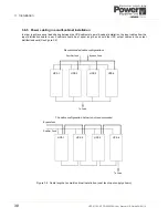
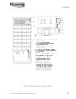
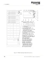
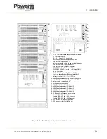
3.7.1 Connecting the input cables
Refer to figures 3.5 to 3.7
(also figures 3.14 to 3.16)
1. Gain full access to the UPS power terminals by removing the aluminium panel at the bottom of the UPS, below the
switch-gear.
2. Connect the earth cable from the mains distribution board to the UPS protective earth terminal (PE).
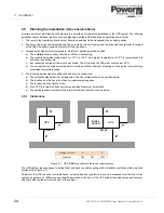
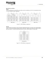
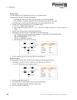
Single input feed (standard)
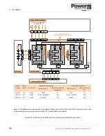
3. Refer to the schematic drawing and connection table in Figure 3.3.
4. Connect the UPS input supply cables to the UPS input power terminals 1L1, 1L2, 1L3 and 1N. Ensure correct
(clockwise) phase rotation.
5. Secure the cables to the fixing rail under the connection terminals.
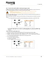
Dual input feed
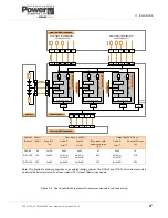
6. Refer to the schematic drawing and connection table in Figure 3.4.
7. The UPS is supplied for single feed input as standard. For a dual feed configuration remove the links between the
UPS power terminals 1L1-2L1, 1L2-2L2, 1L3-2L3 and 1N-2N.
WARNING:
Opening or removing the UPS-covers will create a risk of exposure to dangerous voltages if
power is connected to the UPS.
WARNING:
Do not apply electrical power to the UPS before it has been commissioned.
CAUTION: The input Neutral cable must be unswitched and ALWAYS connected.


