


Figure
2
page 4
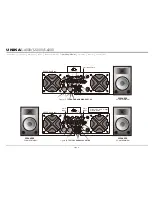
15. Fan Outlet Ports -
Dual high speed cooling fans. Cooling air enters the amplifier through
the front grills and exhausts through the fans. Be sure not to block these ports when
installing the amplifier or other associated equipment. Air must flow unimpeded through
these ports.
16. Channel 2 Balanced 1/4" TRS & XLR Input Connector -
These connectors accept input
signals on balanced TRS and XLR input plugs. Connectors for each channel are in parallel;
the unused connectors may be used for "loop through" connection to other amplifiers.
XLR pin setting: Pin-3/signal Negative, Pin-2/signal Positive, Pin-1/Ground.
TRS pin setting: Tip/signal Positive, Ring/signal Negative, Sleeve/Ground.
17. Channel 2 Frequency Adj. -
This pot adjust the frequency level sent to your speaker on
channel two when using your amplifier in subwoofer mode.
18. Channel 2 Subwoofer Mode On/Off Switch -
Turns the subwoofer mode for channel two
on and off.
19. Channel 2 XLR THRU Jack -
This Jack is used to send a parallel signal from the channel
two input jack to another device or amplifier.
20. Input Gain -
This sensitivity selector sets the input level for rated power output, 0.775V, 1V
or 1.44V.
21. Amp. Mode Selection Switch -
This switch allows the amplifier operating mode from mono
bridge, stereo or parallel mono selection. Amplifiers are factory-configured for Stereo
Mode. See section on Mode Selection for more information.
22. Channel 1 XLR THRU Jack -
This Jack is used to send a parallel signal from the channel
one input jack to another device or amplifier.
23. Channel 1 Subwoofer Mode On/Off Switch -
Turns the subwoofer mode for channel one
on and off.
24. Channel 1 Frequency Adj. -
This pot adjust the frequency level sent to your speaker on
channel one when using your amplifier in subwoofer mode.
25. Channel 1 Balanced 1/4" TRS & XLR Input Connector -
These connectors accept input
signals on balanced TRS and XLR input plugs. Connectors for each channel are in parallel;
the unused connectors may be used for "loop through" connection to other amplifiers.
XLR pin setting: Pin-3/signal Negative, Pin-2/signal Positive, Pin-1/Ground.
TRS pin setting: Tip/signal Positive, Ring/signal Negative, Sleeve/Ground.
26. Reset Button -
This button is designed to protect the amplifier and your speakers in the
event of an AC overload. In the event of an electrical overload, the circuit breaker will pop-
out. Push it in to reset the breaker, if the breaker continues to pop, stop using the amplifier
and contact customer service.
27. Channel 2 Speakon Output -
Use pins 1+ and 1- of this 4-pole Speakon connector to
connect to your speaker's Speakon input jack.
28. Channel 1 Speakon Output -
Use pins 1+ and 1- of this 4-pole Speakon connector to
connect to your speaker's Speakon input jack.
29. Channel 2 Output Jack / 5-Way Binding Post -
Connect to your speakers input jack. Red
is positive signal and Black is negative signal.
30. Channel 1 Output Jack / 5-Way Binding Post -
Connect to your speakers input jack. Red
is positive signal and Black is negative signal.
31. AC Power Input -
Plug this cable in to a standard 110V or 220V wall outlet. Be sure that
supplied voltage matches that of the required voltage of your amplifier. Never plug your
amplifier in to a wall outlet that does not match the required voltage of your amplifier,
serious damage may occur to your unit.
S-4000/S-5000/S-6000 REAR PANEL
UNiKA
S-4000/S-5000/S-6000
15
15
Introduction Front Panel
Set Up Speakon Assembly Operating Modes Protection Features Specifications
Rear Panel
BRIDGE
MONO
_
+
+
+
_
CH-1
CH-2
_
PINOUT
1+
1-
POS NEG
CH- 2
PINOUT
2+
2-
POS NEG
CH- 2
1+
2+
POS NEG
BRIDGE
1+
1-
POS NEG
CH- 1
H-2
C
K
C
O
L
H-1
C
K
C
O
L
PARALLEL
STEREO
BRIDGE
THRU
PUSH TO RESET
FREQUENCY
20 Hz
20 Hz
200 Hz
200 Hz
FREQUENCY
CH-2
CH-1
~120VAC 60Hz
THRU
INPUT
GAIN
INPUT
NORMAL
SUB
0.775V
1V
1.44V
NORMAL
SUB
INPUT
29
27
28
18
17
24
21 22
20
25
26
31
16
19
23
30
Содержание S-4000
Страница 16: ...Professional Power Amplifiers UNiKA ...