


Introduction Front Panel
Set Up Speakon Assembly Operating Modes Protection Features Specifications
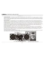
Rear Panel
Figure
2
page 4
10. Fan Outlet Ports
- Cooling air enters the amplifier through the front grills and
exhausts through the fans. Be sure not to block these ports when installing the
amplifier or other associated equipment. Air must flow unimpeded through these
ports.
11. Channel 2 Balanced 1/4" TRS & XLR Input Connectors
- These connectors accept
input signals on balanced TRS and XLR input plugs. See the figures 3-5 for
information on polarity. Connectors for each channel are in parallel; the unused
connectors may be used for "loop through" connection to other amplifiers.
XLR pin setting: Pin-3/signal Negative, Pin-2/signal Positive, Pin-1/Ground.
12. Channel 2 Subwoofer Mode On/Off Switch -
Turns the subwoofer mode for channel
two on and off.
13. Channel 2 Frequency Adj. -
This pot adjust the frequency level sent to your speaker
on channel two when using your amplifier in subwoofer mode.
14. Channel 1 Frequency Adj.-
This pot adjust the frequency level sent to your speaker
on channel one when using your amplifier in subwoofer mode.
15. Channel 1 Subwoofer Mode On/Off Switch -
Turns the subwoofer mode for channel
one on and off.
16. Channel 1 Balanced 1/4" TRS & XLR Input Connectors
- These connectors accept
input signals on balanced TRS and XLR input plugs. See the figures 3-5 for
information on polarity. Connectors for each channel are in parallel; the unused
connectors may be used for "loop through" connection to other amplifiers.
XLR pin setting: Pin-3/signal Negative, Pin-2/signal Positive, Pin-1/Ground.
17. Channel 2 XLR THRU Jack
- This Jack is used to send a parallel signal from the
channel 2 input jack to another device or amplifier.
18. Mode Selection Switch
- This recessed, three-position switch configures the
amplifier for Stereo, Parallel or Bridged Mode operation. Amplifiers are factory-
configured for Stereo Mode. See section on Mode Selection for more information.
19. Channel 1 XLR THRU Jack -
This Jack is used to send a parallel signal from the
channel 1 input jack to another device or amplifier.
20.
Reset Button -
This button is used to reset the breaker.
21. Channel 2 Speakon Output -
Use pins 1+ and 1- of this 4-pole Speakon connector to
connect to your speakers input jack.
22. Channel 1 Speakon Output -
Use pins 1+ and 1- of this 4-pole Speakon connector to
connect to your speakers input jack.
23. Channel 2 Output Jack / 5-Way Binding Post -
Connect to your speakers input jack.
Red is positive signal and Black is negative signal.
24. Channel 1 Output Jack / 5-Way Binding Post -
Connect to your speakers input jack.
Red is positive signal and Black is negative signal.
25. AC POWER Cord
- Plug this cable into a standard 110V or 220V wall outlet. Be sure
that the supplied voltage in your area matches the amplifiers required voltage. Never
plug your amplifier into a wall outlet that does not match the required voltage of your
amplifier, serious damage may occur to your unit.
MP-5000 REAR PANEL
UNiKA
MP-2800/MP-4000/MP-5000
13
24
23
2
1
10
2
2
20
25
19
18
17
15
14
1
2
10
PARALLEL
STEREO
BRIDGE
NORMAL
FREQUENCY
NORMAL
SUB
WOOF
FREQUENCY
CH-1
20 Hz
20 Hz
200 Hz
200 Hz
CH-2
INPUT BALANCE
INPUT THRU
CH-1
CH-2
PUSH TO RESET
1
2
3
HOT
COLD
GND
BRIDGE
MONO
_
+
+
+
_
CH-1
CH-2
_
PINOUT
1+
1-
POS NEG
CH- 2
PINOUT
2+
2-
POS NEG
CH- 2
1+
2+
POS NEG
BRIDGE
1+
1-
POS NEG
CH- 2
SUB
WOOF
H-2
C
K
C
O
L
H-1
C
K
C
O
L
CAUTION
MINIMUM LOAD IMPEDANCE
2 OHM PER CHANNEL
4 OHM BRIDGE
Made in Taiwan
S/N.:
~120V 60 Hz
4200 WATTS
1
1
16
Содержание MP-2800
Страница 16: ...Professional Power Amplifiers UNiKA...


